25
Wired Remote Controller
Table 22 —Applicable Models for VRF Indoor Units
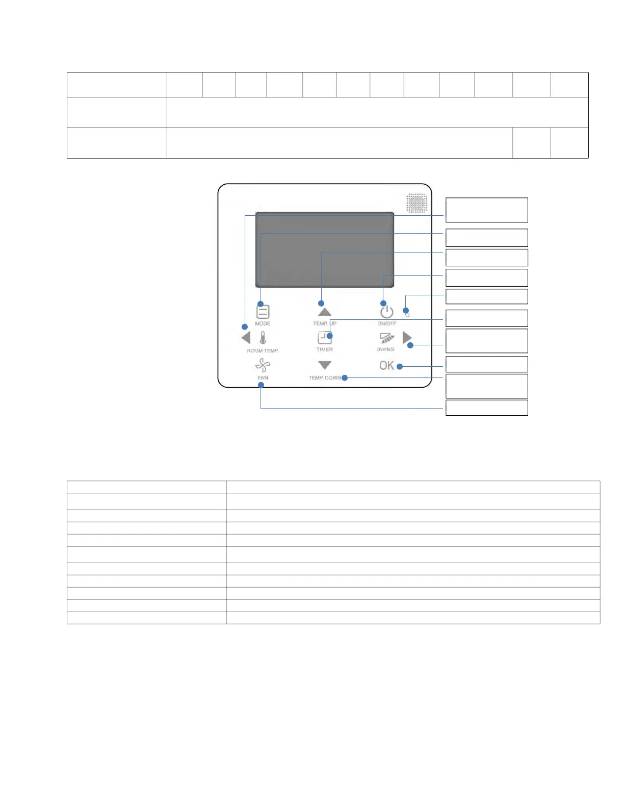
Fig. 37 —Names and Functions—40VM900002 (Non-Programmable Controller)
Table 23 —Functional Description
MODEL SERIES 40VMF 40VMC 40VMI 40VMW 40VMM 40VMU 40VMH 40VMV 40VML 40VMR 40VMA ERV
Remote Controller
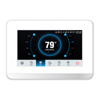
(Programmable Controller)
40VM900003
Remote Controller
(Non-Programmable
Controller)
40VM900002 X X
BUTTON DESCRIPTION
1. MODE
Selects the
running mode
2. TEMP. UP button Increases the set temperature
3. ON/OFF button Powers the IDU on/off
4. LED (green) Stays solid green when the unit is powered on and blinks if there is an error
5. Left button/ROOM TEMP button
Checks the room temperature
/ selects options to the left
6. TIMER button Open timer settings
7. Right button / SWING button Sets the swing location and starts automatic swing/selects options to the right
8. FAN Selects the running mode
9. TEMP. DOWN button Reduces the set temperature
10. OK button Confirms selection
5. Lef t button/
ROOM TEMP button
1. MOD E
2. TEMP. UP button
4. LED
6. TIMER button
7. Right button/
SWING button
10. OK button
9. TEMP. D OW N
button
8. FAN
3. ON/OFF button
 Loading...