26
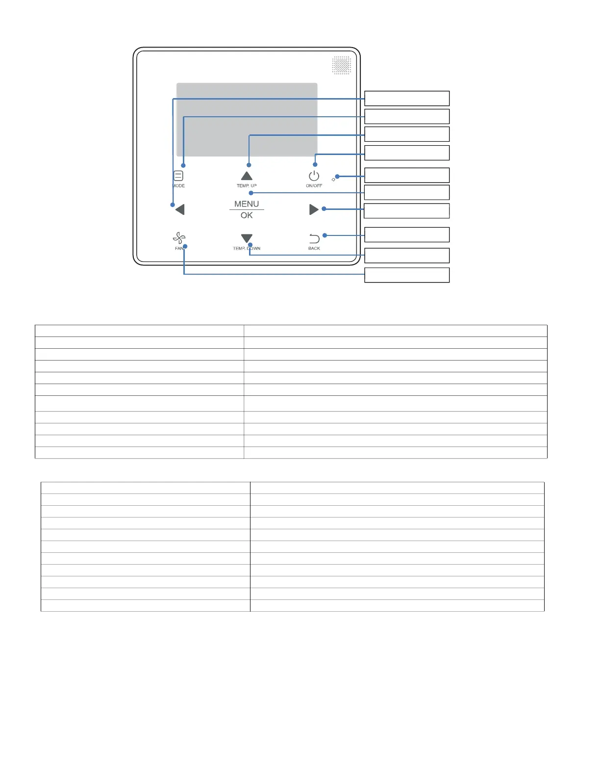
Fig. 38 —Names and Functions—40VM900003 (Programmable Controller)
Table 24 —Functional Description
Table 25 —Main Functions
BUTTON DESCRIPTION
1. MODE Selects the running mode
2. TEMP. UP button Increases the set temperature
3. ON/OFF button Powers the IDU on/off
4. LED (green) Stays solid green when the unit is powered on and blinks if there is an error
5. Left button Selects options to the left
6. MENU/OK button
Enters the menu/sub-menu;
Confirms selection
7. Right button Selects options to the right
8. FAN Selects fan running speed
9. TEMP. DOWN button Reduces the set temperature
10. BACK button Returns to the previous level
MAIN MENU SERVICE SETTINGS MENU
Louver Room temperature sensor location
Schedule Room temperature sensor offset
Date and time Set point limit
Daylight saving time Thermal sensitivity adjustment
Display configuration Changeover time
Room temp Anti-cold blow
Lock Terminal fan configuration
Operation lamp Thermo-off fan speed setting
Touch tone Static pressure
Advanced information Occupancy sensor, Dry contact, IDU addressing
5. Lef t button
1. MODE button
4. LED
2. TEMP. UP button
6. MENU/OK button
7. Right button
10. BACK button
9. TEMP. DOWN button
8. FAN button
3. ON/OFF button
 Loading...


