Installation Electrical connections
Install the unit according to the national standards on plants.
Connect the power supply L (LINE), N (NEUTRAL) and
(GROUND) to
terminal 16 as shown in the wiring diagram. Respect the poles shown on
the bottom of the electric panel.
See gures 27 and 28. All units are equipped with a fuse that protects
the machine/controls. If this fuse needs to be replaced, refer to table II
(POWER SUPPLY FUSE).
IMPORTANT:
• Makeearthconnectionpriortoanyotherelectricalconnections.
• Disconnectthepowersupplytoallcircuitspriortohandlingany
electrical components.
Remove the control box panel casing by means of the xing screw/s.•
According to the installation instructions, the disconnecting switches •
from the mains power supply should have a contact gap (4 mm)
such that total disconnection can be ensured under the conditions
provided for by overvoltage class III.
All fan coil connecting cables as well as accessory wires must be •
of the H05 VV-F, type with PVC insulation according to the EN
60335-2-40 standard.
For the unit power supply, it is recommended to use cables with a •
minimum size of 3G1.5 mm
2
.
For units equipped with electric heater, refer to table III (Electric •
heater datasheet) for the sizes of the power supply cables.
After making all electrical connections do not forget to close the •
control box panel using the special protective cover and to x it by
means of the screw/s previously removed.
Control box panel:
The control box panel is always positioned opposite the water
connections.
For the units 42N-S there are available tree types of control box panels:
1) Control box panel for standard units (see g. 27)
2) Control box panel for unit with low power electric heaters (see g. 28)
3)
Control box panel for unit with high power electric heaters (see g. 28b)
Inside the control box panel there are the terminal blocks for making the
connections as shown in the attached wiring diagrams.
42N-E units (equipped with Low Energy Consumption fan motor)
are driven by the Carrier NTC control. For further details on electrical
connections of the above-mentioned units refer to the additional
manual (NTC control) supplied with the unit.
IMPORTANT:
on the units equipped with high power electric heaters > 2000W
size S30-S45, the electrical heaters supply must be separated from
that of the unit. Inside the control box panel (g. 28b) there are the
terminal blocks for the electrical connections.
Controls (type A – B)
Upon request, the fan-coils of the 42N series can be equipped with one
of the two types of controls available.
The controls are electronic with microprocessor regulation (A and B).
The two control models can be mounted either onboard the machine or
on the wall.
Each control regulates a single fan coil (alternatively with a relay
board it is possible to regulate several units with a single control see
accessories).
All controls must be opened and installed only by qualied personnel as
they contain electrical and electronic components, connected to 230V
power supply.
WARNING:
Disconnect the power supply before opening the control cover.•
All inputs (external contact, seasonal changeover etc.) must be •
electrically insulated consistent with 230V requirements.
Floor-mounted vertical unit (See g. 18)
The unit is provided with supporting feet and cover panels (models with
cabinet).
For positioning and drilling use the template printed on the packaging.•
Drill four holes for the screw anchors close to the upper and lower hooks.•
Install the supporting feet by inserting the special tab into the •
corresponding slot on the unit plate (See g. 17)Centre the two
indentations and secure each supporting feet using the corresponding
clips supplied with the kit.
If a baseboard is mounted onto the wall, remove the pre-cut tab from •
the cover panel. Install the cover panels by hooking them to the slots
on the cabinet lower part and secure them with the screws supplied.
Position unit to wall and secure it with screws. To facilitate cabinet •
installation, it is suggested to use athead screws.
To complete the installation make electrical and water connections as •
per the diagram inside the control box panel. When all connections
have been made, install the cabinet as previously described.
Start-up of all units supplied without cabinet (42NF – 42NP) should •
be carried out by the installer according to safety directions for easy
access to live and moving parts provided for by EN 60335-1 and EN
60335-2-40 standards (see Fig. 18A and 18B but only as an indicative
example).
WARNING: With wall-to-wall carpet the hole points must be moved up
by 10 mm (as indicated on the template).
Wall-mounted vertical unit (See g. 19)
This unit is not provided with supporting feet and cover panels.•
Install the unit as indicated above and keep it at least 100 mm from •
the oor.
Ceiling-mounted horizontal unit
Use the template printed on the packaging for ceiling mounting of the •
unit.
Units with cabinet 42NM and 42NZ
Make four holes for the screw anchors near the four hooks g. 19 (2 •
side and 2 front hooks).
Concealed units 42NF and 42NP
Attach the two brackets supplied for horizontal installation to the unit, •
securing them with the screws as shown in gure 20.
Make four holes for the screw anchors near the four side hooks.•
Hook the unit on the screw anchors in the ceiling and adjust the 4 •
screws.
Make certain the fan coil is horizontally levelled.•
Make electrical and water connections and install the cabinet.•
Condensate drain
Coil surface condensation formed during the cooling cycle is collected
in a pan purposely placed under the coil and then drained out through a
drain pipe tted on the coil connection side.
A simple exible tube which ts Ø 20 mm is recommended. To facilitate
correct condensate draining, make sure that the drain pipe is not bent or
restricted and that it has the required slope (at least 2%) along its length.
A drain trap is recommended (See g. 9)
Checking
Before unit operation verify that the water ows into the internal
condensate drain pan by pouring some water into it.
If problems are detected, check the drain pipe slope and look for
possible obstructions.
Water connections
Water piping can enter either from the oor or from the wall. Leave the
space shown in the gure 21-22. The unit coil can be supplied with water
connections positioned as requested. However eld conversion of the
connections is achieved quite simply as follows:
Remove the control box panel;•
Unscrew the 6 self-threading screws and remove the front drain pan;•
Unscrew the two screws holding the heat exchanger to the structure, •
necessary for earthing the coil;
Remove the coil by unhooking it with the rubber tabs and turn it •
horizontally through 180°;
Place the coil into its new position by hooking it using the special •
rubber tabs;
Ret the front drain pan with the 6 self-threading screws;•
Retighten the two screws holding the heat exchanger to the structure, •
necessary for earthing the coil;
Position the control box panel opposite the coil connections;•
Pass the sensor through the special hole and seal with sealing material •
in the tangential fan versions;
Position the control into the tabs provided,, blocking it with the •
supplied metal plate (see paragraph “Controls”);
Change the position of the condensate drain closing plug of the drain •
pan and put it on the same side of water connections.
NOTE: The connection pipes must be insulated with a condensation-
proof material such as polyurethane, propylene or neoprene of 5 to 10
mm thickness.
Automatic water valves
(See g. 23-24-25)
The fan coils can be equipped with valves, both in 2-pipe or 4-pipe
versions.
We recommend using the valves in order to prevent condensate
formation on the unit when the fan is not working and room
humidity is very high.
The valve heads are thermal type with 230V power supply, average
consumption 5 VA, maximum operating pressure 1400 kPa.
opening time depends on the temperature and is from 120 to 240
seconds. The tightness of the connections is ensured by a rubber sealing
(O-RING) inserted in the connection (tightening torque 30 Nm).
If valves are installed by the installer (accessories), do not forget to use
the (O-RING) sealing ring supplied.
The motorized valves can be 3-way with bypass or 2-way. Make sure that
all unit pipe connections are aligned and well supported, to prevent
abnormal strains on the unit. Check for leaks after the system has been
lled with water. Do not forget to t the auxiliary pan under the valve
assembly by inserting the drain pipe into the corresponding hole or the
valve insulating shell. For 2-way valve units, close the free space of the
insulating shell using the plug supplied (fog. 26c). Fix the insulating shell
using nylon strips (g. 26a). Make sure the pipe insulation is correctly
positioned inside the shell (g. 26a) to prevent condensate on the pipes.
The manufacturer cannot guarantee seal quality and tightness of the
valve group provided by the installer (which is therefore not factory
tested). The manufacturer thus declines all responsibility for possible
malfunction of said items and for damage resulting from leaks in said
items.
ATTENZIONE: Dopo aver posizionato il quadro elettrico sul lato
opposto, ricordarsi di eettuare ilcollegamento di terra alla
struttura dell’unità.
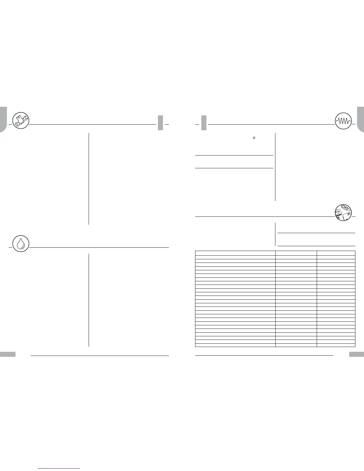
Control functions Type A Type B
ON/OFF
Three fan speeds manually selected
Fan speed automatically selected
Temperature selector
Blue LED – cooling operation
Red LED – heating operation
Yellow LED – automatic seasonal changeover
Yellow LED – energy saving
Manual seasonal changeover button
Centralised seasonal changeover button
Automatic seasonal changeover button
Energy saving button
Return air temperature sensor
Temperature sensor located on the board
Cooling / heating valve (2-pipe)
Heating valve (4-pipe)
Cooling valve (4-pipe)
Electric heater
Frost-protection
External contact
Water minimum temperature sensor
Air sampling (periodic fan starting)
Continuous ventilation
Temperature block
Autotest
 Loading...


