Controls
Low Energy Consumption Fan Motor
Electric heaters are controlled by “B”-type CARRIER control.
The electric heaters are equipped with two safety thermostats, one
with automatic reset, the second with manual reset, to protect the unit
against overtemperature that may happen in case of incorrect lter
cleaning or obstructions of the air ow.
NOTES:
In the size 15 unit with “HIGH -LOW POWER” heating element, the •
ULOW speed wire (RED MOTOR WIRE) must be disconnected and
insulated.
The LOW SPEED WIRE (YELLOW MOTOR WIRE) must be connected
in its place.
In case of failure in the electric fan, replace the electric heater too. •
Only qualied personnel should carry out this operation.
T-o access the control box panel, remove the screw located at the
bottom of the cover and delicately bend the tab to remove the cover.
Connect the power supply to the electric heater terminal. Size the
cables according to current drawn (see table III “Technical data of
electric heater).
It is important not to obstruct the supply or air ow and to
periodically check that the lter is clean.
NOTE:
The simultaneous use of hot water and electric heater is possible
in “ONLY LOW POWER” mode. Electric heaters and hot water can
not be used in high power mode. To operate the additional heating
function you need to buy the 42N9084 kit and connect the special
sensor as described in the installation manual. After this, the
corresponding dip switch no. 5 of the type B control must be set to
ON.
Fan Motor
The units have tangential/centrifugal motors with selectable speeds.
There are 5 speeds available:
Ultra Low- Low-Medium-High-Super High.
All machines are congured at the factory as follows:
ULTRA LOW - MEDIUM – SUPER HIGH.
In the case of particular needs, it is possible to move the speed
connections (with Faston quick-connectors) following the enclosed
table and relative drawing (see Fig. 29).
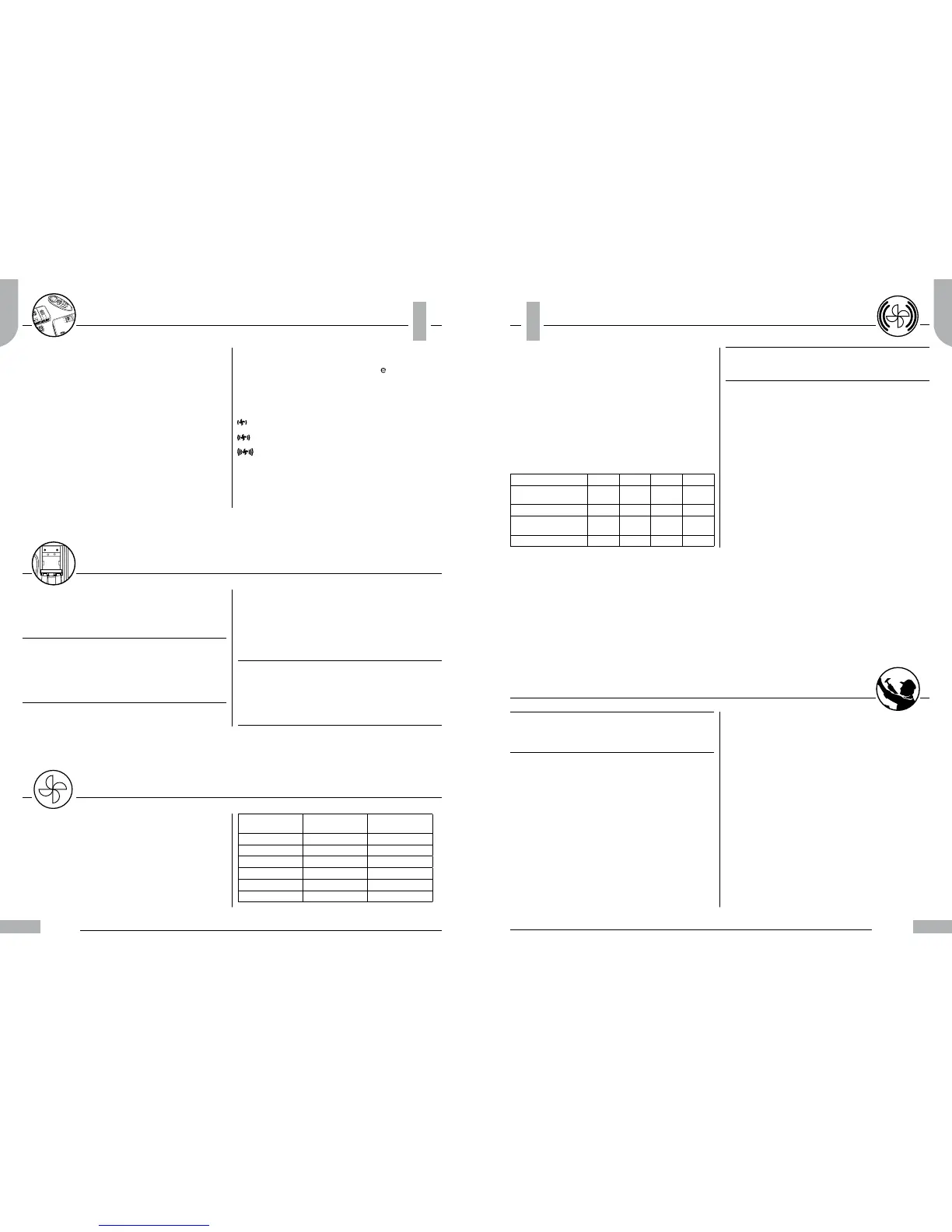
MOTOR SPEED CABLE COLOR
ENGINE
FACTORY
CONNECTION
ULTRA LOW RED RED
LOW YELLOW
MEDIUM WHITE WHITE
HIGH ORANGE
SUPER HIGH BLACK BLACK
MOTOR NEUTRAL BLUE BLUE
Low Energy Consumption Fan Motor version
The fan coil units of the series 42NE… can ensure a 0% - 100% constant
air ow modulation (and therefore the thermal and refrigerating
capacity) thanks to the Inverter technology combined with the last
generation of high energy-ecient electric motors (EC brushless). This
enables a constant control on the power supplied according to the
room that need to be conditioned. The result is 50% electric energy
saving compared to traditional 3-speed asynchronous motors and a
considerable reduction of acoustic emissions.
The new range of fan coil units 42NE is equipped with 4 Low Energy
Consumption Fan Motors one of which is tangential and 3 centrifugal.
The table below shows the electrical characteristics of the four types of
motors.
NOTE:
The values showed on table are reported only at the Low Energy •
Consumption Fan Motor to they are necessary add the control
input power which correspond about 5W
The fan coil units of the series 42NE are submitted by Carrier to the NTC
control (see attached additional manual) for best regulation of room
temperature.
No further electrical connections are necessary (beside power supply
and communication bus)
for this unit.
All connections between electric components and motor are factory
made.
In the centrifugal units, the inverter regulation board is directly installed
on the motor frame and protected by a metal case.
See g. 42-43.
Due to the lack of space, in the tangential units the regulation board is
installed in the electric panel of the NTC controller.
See g. 41.
42NE E19 E29 E39 E49
MINIMUM SPEED
POWER INPUT (W)
4,5 4,6 6,6 9
CURRENT DRAWN (A) 0,057 0,061 0,076 0,09
MAXIMUM SPEED
POWER INPUT (W)
14,5 14,5 30,1 60,9
CURRENT DRAWN 0,144 0,144 0,271 0,514
Diagnostic warnings
The following alarm situations are indicated:
Defective sensors: the red LED ashes.
Possible causes:
failure or short circuit of internal or remote sensor;•
failure or short circuit of water temperature sensor (optional and only •
on type “A” control).
Incorrect conguration
The yellow LED ashes.
This happens when:
in type “A” control, both centralised seasonal changeover signals “RC •
and RH” are enabled.
Autotest
The autotest function is activated by holding the seasonal changeover
button pressed and at the same time pressing the “
” button three
times within 1 second.
In this way it is possible to check the starting of all fan coils.
The blue and red LEDs will begin to ash.
Each of the various units will be activated for 10 seconds in the following
sequence:
Low fan speed.
Medium fan speed.
High fan speed.
CV Motorized cold-water valve.
HV Motorized hot-water valve, or electric heater (only type “B”
control versions).
Elapsed 1 minute the control ends the test mode.
Electric heater
Maintenance
IMPORTANT:
The following maintenance operations should be carried out by
qualied personnel.
Disconnect the mains power supply prior to any maintenance
operations or prior to handling any internal parts of the unit.
Air lter
Check and make sure the lter is cleaned every two months or more
often if unit is located in a dusty room.
A dirty lter reduces the air ow and unit eciency.
To inspect lter proceed as follows:
switch the unit o;•
loosen the two screws located at the base of the unit and the •
corresponding plates and the corresponding plates or the rear closing
grille (if installed);
lower the two guides and withdraw lter (See g. 38)•
clean the lter gently with soapy water or with a vacuum cleaner;•
reinsert and position the lter in the guides, keeping the •
photocatalytic lter tabs upwards as illustrated (See g. 39)
return the lter guides to their original position (See g. 40)•
tighten the screws and associated plates.•
It is advisable to clean and if necessary replace the air lter before
the winter season.
Condensate draining
During the summer season check that the condensate drain is free from
dust and lint that could clog it, causing condensate water overow.
Heat exchanger coil
At the beginning of any winter and summer season it is advisable to
check that the coil ns are not clogged with dust, lint or other foreign
matter.
Clean the heat exchanger after having removed the supply grille, taking
care not to damage the ns.
Motor
The motor is permanently lubricated.
Therefore no periodical maintenance is required.
Fan Motor
 Loading...


