16
Speed Controller
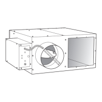
Each Carrier fan powered air terminal unit is equipped with a fan
SCR speed controller, located on the bottom of the control box.
The SCR can be adjusted in the field.
NOTE: The 45J size 7 unit and 45Q size 4 unit have two SCR
speed controllers, one for each fan. One SCR is located in the stan-
dard position at the bottom of the control box; the other is at the
top of the control box.
The fan airflow output is dependent on the setting of the controller
and the downstream static resistance.
1. To increase the fan speed (RPM), turn the slotted adjust-
ment on the controller clockwise toward the “HI” marking
printed on the controller face plate (see to Fig.
11).
2. To decrease the fan speed (RPM), turn the adjustment
counterclockwise toward the “LO” marking. (see Fig.
11).
Fig. 11 — Fan Speed Controller
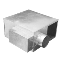
Table 14 — 45R Parallel Fan Powered Terminal Unit
a,b,c
a. 45R maximum primary airflow (CFM) is based on 1.00 in. wg differential pressure signal from inlet airflow sensor.
b. Minimum recommended airflow (CFM) is based on 0.03 in. wg differential pressure of the inlet airflow sensor, or 0 airflow. 0.03 in. wg is equal to 15% to 20% of the
nominal flow rating of the terminal. Less than 15% to 20% may result in greater than +5% control of box flow.
c. 45R maximum/minimum fan airflow is based on 0.25 in. wg external (downstream) static pressure, respectively.
45R WITH PSC FAN MOTOR
UNIT
SIZE
INLET SIZE
(in.)
FAN AIRFLOW PRIMARY AIRFLOW
MOTOR HP
MOTOR AMPS
MIN MAX MIN MAX 120V 208/240V 277V
2
6
350 665
52 or 0 515
1/6 3.7 1.5 1.48 92 or 0 916
10 143 or 0 1432
4
8
420 855
92 or 0 916
1/4 5.6 2.5 2.010 143 or 0 1432
13.5 x 8 206 or 0 2062
45R WITH ECM FAN MOTOR
UNIT
SIZE
INLET SIZE
(in.)
FAN AIRFLOW PRIMARY AIRFLOW
MOTOR HP
MOTOR AMPS
MIN MAX MIN MAX 120V 208/240V 277V
2
6
125 820
90 or 0 515
1/3 5.0 3.3 2.68 160 or 0 920
10 250 or 0 1430
4
8
135 885
160 or 0 920
1/3 5.0 3.3 2.610 250 or 0 1430
8 x 14 360 or 0 2060
CAUTION
The minimum stop on the speed controller is factory set at an
internal minimum stop to prevent damage to the motor. Do not
attempt to override this minimum stop or electrical damage to
the fan motor may result.
LO
HI
U
R
RANCO
MXF-544002-001
1
00533-01
277 V 12L
5 FLA
50
6
Z
 Loading...