9
11. Check all control connections (and/or electric) for proper
installation.
12. Connect electrical power.
Balancing Carrier Fan Terminals
Carrier fan terminal units contain primary air dampers which, un-
der the control of a volume controller, regulate the amount of cold
air distributed to the space.
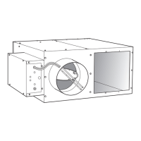
45J,K,Q SERIES FLOW UNITS
The 45J,K,Q series flow terminals direct all primary air through
the unit fan. The terminal is designed to operate with the fan sup
-
plying airflow equal to or greater than the airflow supplied by the
VAV damper. To balance the unit, therefore, it is necessary to first
set the fan flow, and then the VAV damper (primary) flow.
Each control option has specific procedures required for balancing
the unit, but some steps are common to all 45J,K,Q units. The fan
box adjustments described below must be made in conjunction
with the adjustments described in the Speed Controller and Con
-
trol Adjustments section.
The VAV damper airflow may be set at the factory, but the fan air-
flow must be set in the field as described in “Setting of VAV (Pri-
mary) Airflow.”
Setting Fan Airflow
1. Set the controller to provide heating airflow demand only.
Typically, this is accomplished by setting the thermostat to
the highest possible temperature setting.
NOTE: A minimum of 0.1 in. wg downstream static pressure is
required in the duct to ensure proper heater operation.
2. Determine that the VAV valve is fully closed and that the
fan is rotating in the proper direction. (If the VAV damper
is open when the fan is started and there is primary air in
the system, the fan may start and run backward.)
3. Using a flow hood or duct traverse, determine the deliv-
ered fan airflow (cfm).
NOTE: Both flow hood and duct traverse are subject to measure-
ment errors. Be sure that all applicable measurement precautions
are taken.
4. Compare the actual cfm in heating mode to the designed
airflow. If there is a minimum setting for the VAV damper
in heating mode (as recommended by ASHRAE [Ameri
-
can Society of Heating, Refrigeration, and Air Condition-
ing Engineers] Standard 62), this quantity is included in
the total measured heating airflow to determine if the
desired induction airflow level has been met.
5. Adjust the fan SCR at unit control box to achieve the
desired airflow rate. Refer to Tables
9-14 to ensure airflow
through electric heaters meets the requirements before
operating the heater.
Setting of VAV (Primary) Airflow
Adjustment of Set Points
Each 45J, 45K, and 45Q supplied with controls is equipped with a
pneumatic or electronic volume controller which regulates the
quantity of cold primary air entering the terminal and the condi
-
tioned space. If required airflow levels are specified with the job
order, the minimum and maximum cfm levels will be set at the
factory where applicable. If minimum and maximum levels are
not specified, a default value of 0 is used for minimum setting at
the factory. Other settings of minimum and maximum primary air
-
flow must be set in the field. Airflow (cfm) ranges for the primary
air damper are shown in Tables
9-14. The minimum primary air-
flow (other than zero) is the minimum flow rate controllable by
the unit volume controller. The primary air damper can be set at
zero for shutoff or at the minimum cfm listed.
Field Adjustment of Minimum and Maximum Airflow Set
Points
Each 45J, 45K, and 45Q unit is equipped with a centerpoint aver-
aging airflow sensor which provides an amplified differential
pressure that is proportional to the unit airflow. Output from this
probe is used to provide a flow signal to both pneumatic and elec
-
tronic controls. Unit airflow (cfm) can be read directly from the
flow probe on the unit (refer to Fig.
9).
1. With the unit airflow from the fan set, turn on primary
(VAV) air supply.
2. To set cfm in the field, connect a gage to the flow probe at
the provided ‘T’ taps, and check the differential pressure.
(Alternately, the total flow may be measured, and the pre
-
viously determined fan induction flow rate may be sub-
tracted from the total flow to determine VAV flow.
However, for low primary settings, this may not be as
accurate as the flow tap method.)
3. If a minimum VAV flow is required in heating mode,
adjust the volume until the differential pressure corre
-
sponds to the cfm required.
4. Set the controller to provide maximum cooling demand.
This is typically accomplished by first setting the thermo
-
stat to the lowest possible temperature setting.
a. In most series fan boxes, the primary airflow rate is
equal to the fan induction flow; in these cases, adjust the
volume controller until a balance is achieved between
fan induced airflow and primary airflow. When a bal
-
ance exists, a strip of paper hung at the induction port
should hang straight down, and neither be blown in or
out of the unit.
b. If the primary airflow desired is less than the fan induc-
tion flow, adjust the volume controller until the differen-
tial pressure (measured through the flow probe as
described above) corresponds to the cfm required. Verify
that induction exists through the inlet ports, using the
paper strips as described above. When induction exists,
the paper strip should be pulled into the unit.
5. Return all reheat options to normal connections.
6. Cap the ‘T’ taps.
7. Reset the thermostat to a normal setting.
NOTE: It is normal for the total airflow to the room to increase
slightly in full cooling mode.
NOTE: If the unit has electric heat or hot water heat, temporar-
ily disable these functions before balancing the fan.
If unit has optional electric heat disconnect downstream of fan
motor connections to power, open disconnect.
If unit does not have optional electric heat disconnect, remove
one electric heat power line connection. Be sure to insulate
loose line from ground wire or other wires.
 Loading...