37
SERVICE
Controls
No periodic preventive maintenance is necessary.
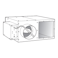
Fan Motor and Wheel
The fan motor and wheel are accessible from the bottom of the
unit. Remove the bottom panel to check the wiring or remove the
fan wheel or motor.
The PSC motors are equipped with long life sleeve bearings with
non-detergent SAE 20 oil biannually.
The ECM motor has permanently lubricated ball bearings that re-
quire NO maintenance.
TO CHECK WIRING
The PSC motor is connected by quick-connect terminals to the ca-
pacitor (brown wire), the housing wire (green ground wire), and
the control box (black wire and white wire). Verify that the fan
motor wiring is correct (refer to Fig.
18-20).
TROUBLESHOOTING
To remove the fan motor and wheel:
1. Disconnect motor wiring.
2. The fan motor and wheel assembly is attached to the dis-
charge panel with 4 hex nuts.
3. Remove the motor by removing the 3 screws that attach
the torsion flex mounts to the inlet ring.
4. Remove wheel by unscrewing the hub set screws that are
accessed through the open end of the wheel.
Fan Motor Wiring
Refer to the fan motor wiring details shown on the wiring dia-
gram attached to the unit. Failure to reconnect the fan properly
can cause damage to the motor and/or serious personal injury.
Fan Motor Maintenance
Unit motors are equipped with permanently lubricated bearings.
Inspect fan and motor assembly for accumulation of dust and dirt
as required by operating environment. Clean as necessary. See
Fig.
18-20 for motor wiring.
Fig. 18 — PSC Motor Wiring Terminal Block —
115 V, Single Phase
Fig. 19 — PSC Motor Wiring Terminal Block —
208/240 V, Single Phase
Fig. 20 — PSC Motor Wiring Terminal Block —
277 V, Single Phase
WARNING
LOCK OPEN AND TAG heater electrical disconnect before
working on this equipment. Otherwise, one leg of the 3-leg
heater remains energized.
WARNING
Disconnect power to unit before touching fan motor wiring, or
electrical shock or personal injury could result.
CRIMPTIE WIRE 1
AND WIRE 4
Green
BLACK #12
BLACK #12
TO
SCR CONTROLLER
BROWN TO
CAPACITOR
WHITE #12 TO
TERMINAL BLOCK/
DISCONNECT SWITCH
GREEN
BLACK #12
BLACK #12
TO
SCR CONTROLLER
BROWN TO
CAPACITOR
WHITE #12 TO
TERMINAL BLOCK/
DISCONNECT SWITCH
BLACK #12
BLACK #12
TO
SCR CONTROLLER
GREEN
BROWN TO
CAPACITOR
WHITE #12 TO
TERMINAL BLOCK/
DISCONNECT SWITCH
 Loading...