8
Fig. 9 — Linear Probe cfm vs Signal Chart
NOTE: For ComfortID™ terminals, all flow sizes are normalized using a single probe multiplier (PMF) for all sizes equal to 2.273.
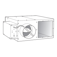
START-UP
General
Before balancing the system, the air handlers must be operating in
accordance with the specifications for air capacity, static pressure,
and temperature. Record data on the startup checklist (Fig.
10).
The following items must be checked:
1. All fans must be running at calculated and specified rpm.
2. Permanent or temporary filters must be clean and installed
where required.
3. All central station dampers must be adjusted and operating
properly.
4. All thermostats must be calibrated and at the desired set-
tings.
5. All ductwork must be tight.
6. All dirt or loose lining must be removed from inside
ductwork.
7. Pumps and sprays, when used, must be in operation.
8. Connections to the coil, when used, must be checked.
9. Water control valve, if used, must be checked.
NOTE: All 45 Series terminal units are shipped with cardboard
packaging rings placed in one side of the blower housing internal
to the blower/motor. These rings are provided to prevent damage
to the motor during shipment. The rings MUST BE REMOVED
prior to operation. The packing rings are accessible through the
terminal’s plenum. Turn the fan wheel by hand to ensure that
blower is free spinning. Carrier will not accept responsibility for
any additional costs for removal of this packaging material.
Remove the bottom access panel to remove the cardboard packing
material.
Initial Start-Up Procedures
NOTE: The following steps MUST be followed in order to prop-
erly operate and service this unit.
1. Disconnect all electrical power to the unit. Failure to dis-
connect the power to the fan box prior to checking and/or
servicing the fan box could result in a serious injury.
2. Verify that the fan box is installed level, and that adequate
mounting support has been provided.
3. Remove motor access panel from the bottom of the fan
box, and also remove the control panel cover.
4. Test the fan motor setscrew. The setscrew should fit
tightly, but it may have come loose during shipment or
installation.
5. Rotate the blower by hand to ensure proper clearance
between the blower and the blower housing.
6. Check the fan box for loose fiberglass insulation, espe-
cially on the electric heater elements or the hot water coils
(if these accessories are installed).
7. Check the control enclosure and remove any debris.
8. Check the induction inlet filter (if provided) for obstruc-
tions, and verify the filter is securely in place.
9. Verify the main power supply to the connection to the fan
box for proper voltage. If the fan box is installed with elec
-
tric heat, the electric heat voltage may exceed the blower
motor voltage requirement. Excessive voltage to the fan
box may seriously damage it. Verify that the DDC (if
equipped) are receiving 24-vac, –15%, +20%.
10. Identify the control system supplied.
Table 8 — Inlet Areas — 45J,K,M,N,Q,R
INLET DIAMETER (in.)
4 5 6 8 10 12 14 16
Inlet Area 0.087 ft
2
0.136 ft
2
0.196 ft
2
0.349 ft
2
0.545 ft
2
0.785 ft
2
1.069 ft
2
1.369 ft
2
cfm at 1 in. wg 230 360 515 920 1430 2060 2800 3660
INLET SIZES 4
56789101214
16 22
40
(19)
50
(24)
70
(33)
100
(47)
200
(94)
300
(142)
500
(236)
600
(330)
1000
(472)
2000
(944)
3000
(1437)
5000
(2360)
7000
(3303)
1.4
1.8
2.0
2.6
3.4
4.6
5.8
6.8
8.2
9.7
11
(108)
229
(169)
358
(243)
515
(331)
702
(432)
916
(547)
1160
(676)
1432
(973)
2062
(1324)
2806
(1730)
3665
(3303)
7000
1.0 (245.5)
.8 (192.0)
.6 (149.3)
.4 (99.5)
.3 (74.5)
.2 (49.8)
.1 (24.9)
.07 (17.4)
.05 (12.4)
.04 (10.0)
.03 (7.5)
CFM (L/s)
VOLTS (DC), ANALOG CONTROLS
INLET AIRFLOW SENSOR
CFM (L/s) @ 1” W.G. SIGNAL
INLET SENSOR P
INCHES W.G. (PASCALS)
IMPORTANT: Before proceeding with start-up, be certain
that voltage, frequency, and phase correspond to unit speci
-
fications. Unless noted, all fan motors are 60 Hz, 115, 208/
240, or 277-v, single-phase ac. electric heat, the electric
heat voltage may exceed the blower motor voltage require
-
ment. Excessive voltage to the fan box may seriously dam-
age it. Verify that the DDC (if equipped) are receiving 24-v
ac, –15%, +20%.
 Loading...