11
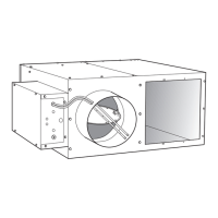
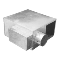
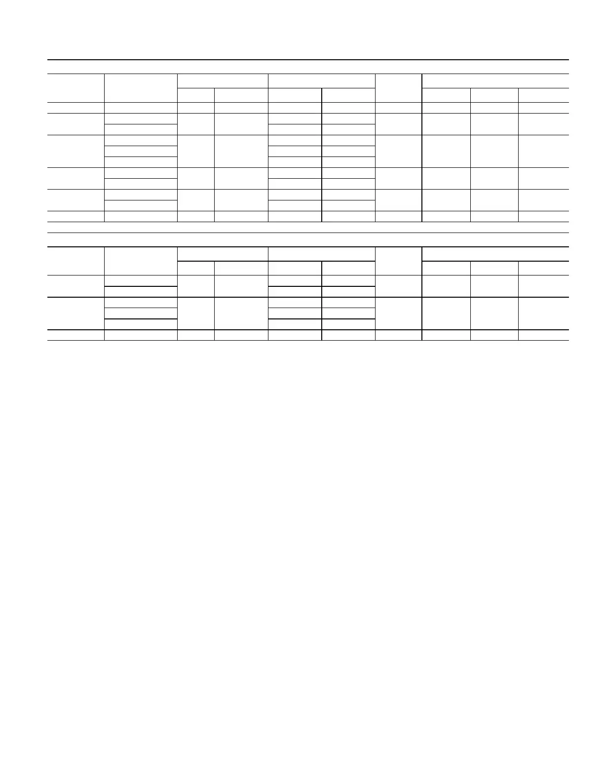
Table 9 — 45J Series Fan Powered Terminal Unit Performance
a,b,c
45J WITH PSC FAN MOTOR
UNIT SIZE INLET SIZE (in.)
FAN AIRFLOW (cfm) PRIMARY AIRFLOW (cfm)
MOTOR HP
MOTOR AMPS
MIN MAX MIN MAX 120V 208/240V 277V
2 6 100 560 52 or 0 515 1/10 1.8 1 0.7
3
6
300 990
52 or 0 515
1/4 3.6 2 1.5
8 92 or 0 916
4
8
550 1440
92 or 0 916
1/4 5 2.8 2.110 143 or 0 1432
12 206 or 0 1440
5
10
1100 2140
143 or 0 1432
1/2 8.3 4.6 3.5
12 206 or 0 2062
6
12
1200 2530
206 or 0 2062
3/4 9.5 5.8 4.4
14 281 or 0 2530
7 16 2100 3900 367 or 0 3665 (2) 3/4 N/A 13.2 9.9
45J WITH ECM FAN MOTOR
UNIT SIZE INLET SIZE (in.)
FAN AIRFLOW (cfm) PRIMARY AIRFLOW (cfm)
MOTOR HP
MOTOR AMPS
MIN MAX MIN MAX 120V 208/240V 277V
3
6
165 1100
52 or 0 515
1/2 7.7 5.0 4.1
8 92 or 0 916
6
10
385 2550
143 or 0 1432
1 12.8 10.5 6.912 206 or 0 2062
14 281 or 0 2550
7 16 685 4550 367 or 0 3665 (2) 1 N/A 21.0 13.8
a. 45J maximum primary airflow (cfm) is set by the maximum induced airflow, which may vary as a function of downstream pressure. Maximum airflow shown is based on
the maximum induced airflow (fan airflow) or 1.00 in. wg differential pressure signal from inlet airflow sensor, whichever is less.
b. Minimum recommended primary airflow (cfm) is based on 0.03 in. wg differential pressure of the inlet airflow sensor, or 0 airflow. 0.03 in. wg is equal to 15% to 20% of
the nominal flow rating of the terminal. Less than 15% to 20% may result in greater than +5% control of box flow.
c. 45J maximum/minimum fan airflow is based on 0.10 in. wg / 0.60 in. wg downstream static pressure, respectively.
 Loading...