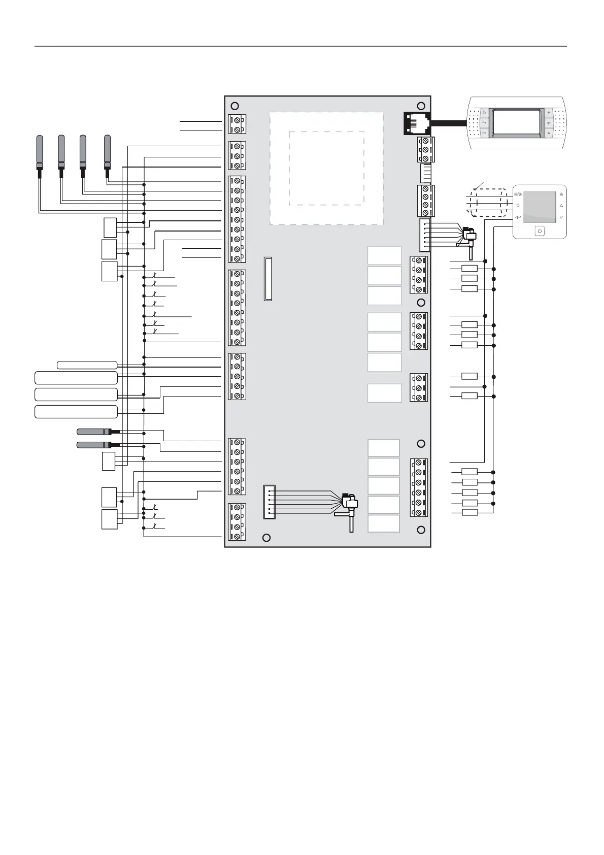
3 - CONNECTIONS
High pressure transducer
circ. 1 (0-5Vdc ratiom.)
C4
NO8
NO9
NO10
NO11
NO12
RX-/TX-
RX+/TX+
GND
Vout
RX-/TX-
RX+/TX+
GND
C1
NO1
NO2
NO3
C2
NO4
NO5
NO6
NO7
C3
NC7
J2 - probe power supply
J3 - analogue
inputs
J4 - digital
inputs
J5 - analogue
outputs
J18 - analogue
inputs
J17
J16 - digital
inputs
J6
J7
J8
(pLAN)
J9
J10
(RS485)
J11
J12 - digital
outputs
J13 - digital
outputs
J14 - digital
outputs
J15 - digital
outputs
L
L
N
N
J1 - power supply
230 Vac
Air quality probe
CO2 (4-20mA)
G
G0
B1
B2
B3
B4
B5
B6
B7
GND
+Vdc
+Vdc
GND
+5 Vref
GND
Y1
Y2
Y3
Y4
DI1
DI2
DI3
DI4
DI5
DI6
DI7
DIC1
B8
B9
B10
B11
B12
GND
DI8
DI9
DI10
DIC2
M
OUT
+5V réf
M
OUT
+V
M
OUT
+V
Indoor fan safety
Compr.1 circ. 2
Reversing valve circ. 2
2-speed outd. fan circ.2
(low-speed)
Compr.2 circ.1
Compr.2 circ.2
Graphic terminal
User terminal
shield
Electronic outdoor fan circ.1
or 2-speed fan (hig-speed)
“50FC”
MEDIUM
board
Low pressure transducer
circ. 1 (0-5Vdc ratiom.)
M
OUT
+5V réf
Suction temp.
probe circ.1
Suction temp.
probe circ.2
High pressure transducer
circ. 2 (0-5Vdc ratiom.)
M
OUT
+5V réf
Low pressure transducer
circ. 2 (0-5Vdc ratiom.)
M
OUT
+5V réf
Compr.1 circ. 1
Reversing valve circ.1
2-speed outd. fan circ.1
(low-speed)
Indoor fan
Elec. heater 1st stage
or gas burner / bolier
Elec. heater 2nd stage
Signal of alarm /
pump / humidifier /
rotary heat exchanger
Mixing temp.
probe (NTC)
Supply temp.
probe (NTC)
Outdoor temp.
probe (NTC)
Return air temp.
probe (NTC)
Ambient temperature
probe (NTC) or outdoor
humidity probe (4-20mA)
Smoke detector
HP pressostat circ.1
Comprs & outd. fan
thermal safety circ.1
Safety line
Clogged filter control
Remote off / on
Outdoor air damper
Water coil 3-WV or propor.
elect. heater or gas burner
Electronic outdoor fan circ.2
or 2-speed fan (hig-speed)
Antifreeze safety (HWC)
Comprs & outd. fan
thermal safety circ. 2
HP pressostat circ. 2
Connector J1
Connector J2
Connector J3 (Analog inputs)
Connector J4 (Digital inputs)
Connector J5 (Analog outputs)
Connector J6
3.1. Main board

 Loading...


