M(G0)+(G)
Tx-
GND
Tx+
120Ω
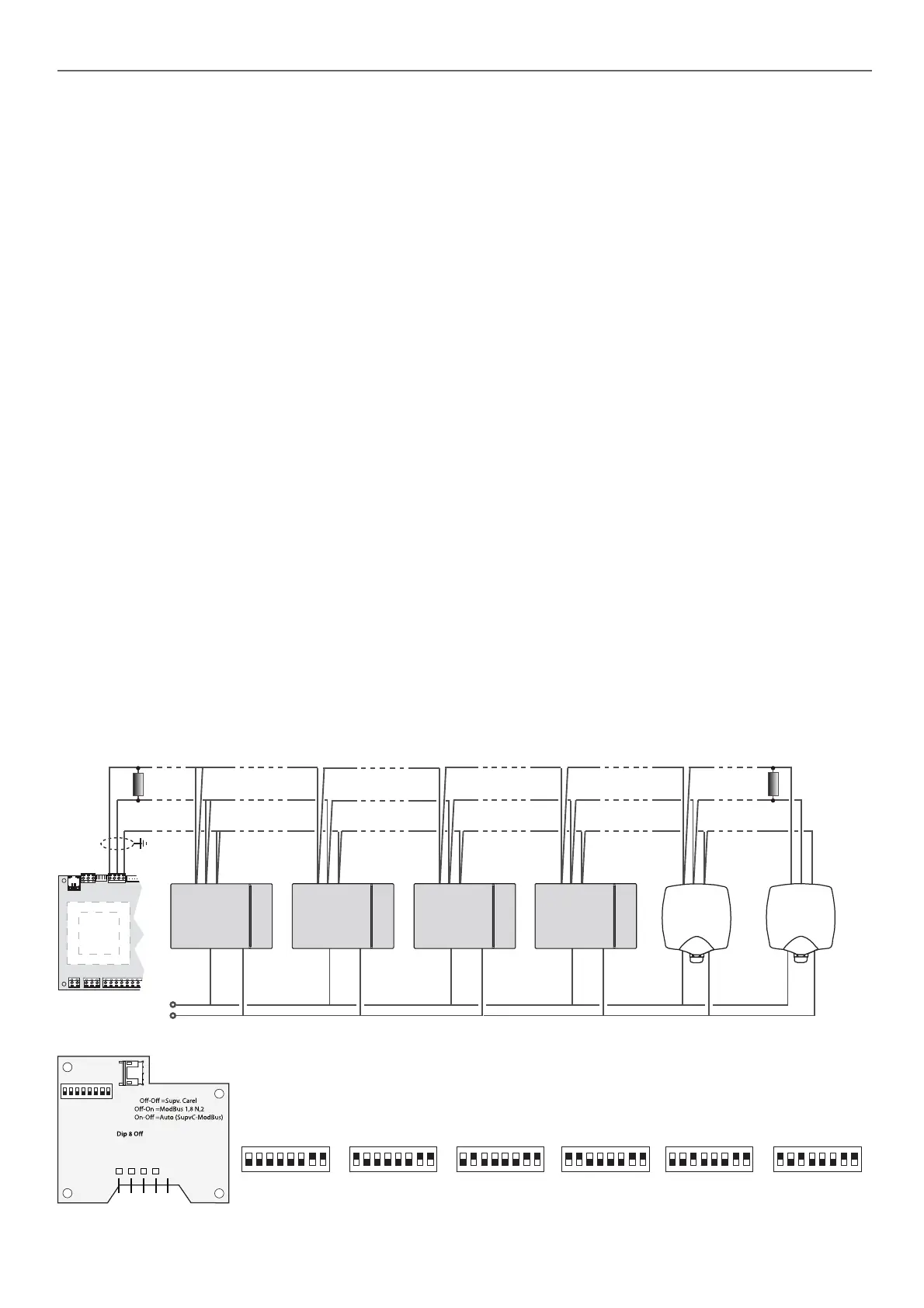
RS485 probes configuration:
Tx-
GND
Tx+
M(G0)+(G)
1
ON
5 6 7 8 2 3 4
Dip 1-5
Address On (128-159)
Dip 6-7
On-On =ModBus 1,8,E,1
= 19200 bps
On = 9600 bps
Tx-
GND
Tx+
M(G0)
+(G)
J10
“50FC”
GND
24 Vac
M(G0)+(G)
M(G0)+(G)
+(G)
M(G0)+(G)
1
ON
5 6 7 8 2 3 4 1
ON
5 6 7 82 3 4 1
ON
5 6 7 8 2 3 4 1
ON
5 6 7 82 3 4 1
ON
5 6 7 8 2 3 4 1
ON
5 6 7 82 3 4
M(G0)+(G)
Important: It is recommended to insert an electrical resistance of 120Ω, between connectors TX+ and TX- of the μPC MEDIUM output
(connector J10) and on the final component of the RS485 network, to avoid potential problems of communication.
Tx-
GND
Tx+
Tx-
GND
Tx+
Tx-
GND
Tx+
Tx-
GND
Tx+
Tx-
GND
Tx+
120Ω
No.2 No.3 No.4No.1
Temp. or
RH+Temp.
probe
Mixing probe
(calculation
of capacities)
Temp. or
RH+Temp.
probe
Temp. or
RH+Temp.
probe
Temp. or
RH+Temp.
probe
Supply probe
(calculation
of capacities)
Ambient probe No.1:
Address: 128
Modbus 1, 8, N, 2
9600 bps
Ambient probe No.2:
Address: 129
Modbus 1, 8, N, 2
9600 bps
Ambient probe No.3:
Address: 130
Modbus 1, 8, N, 2
9600 bps
Ambient probe No.4:
Address: 131
Modbus 1, 8, N, 2
9600 bps
Mixing enthalpic probe:
Address: 132
Modbus 1, 8, N, 2
9600 bps
Supply enthalpic probe:
Address: 133
Modbus 1, 8, N, 2
9600 bps
3.2. Serial connection of RS485 probes to the Field-bus of the control board (optional)
3 - CONNECTIONS
Connector J7
Connector J8
Connector J10
Connector J11
Connector J12 (Digital outputs)
Connector J13 (Digital outputs)
Connector J14 (Digital outputs)
Connector J15 (Digital outputs)
Connector J16 (Digital inputs)
Connector J17
Connector J18 (Analog inputs)

 Loading...


