17
DISCONNECT ALL POWER TO UNIT AND
CONVENIENCE OUTLET. LOCK--OUT AN D TAG--OUT
ALL POWER.
Remove t he blank cover plate at the convenience outlet;
discard the bl ank cover.
Loosen the two screws at the GFCI duplex outlet, unt il
approximately
1
/
2
-in (13 mm) under screw heads are
exposed. Press the gasket over the screw heads. Slip the
backi ng plate over the screw heads at the keyhole slots
and align with the gasket; tighten the two screws until
snug (do not over-tighten).
Mount the weatherproof cove r to the backing plate a s
shown in Fig. 21. Remove two slot fillers in the bottom of
the cover to permit service tool cords to exit the cover.
Check for full closing and latching.
RECEPTACLE
NOT INCLUDED
COVER – WHILE-IN-USE
WEATHERPROOF
BASE PLATE FOR
GFCI RECEPTACLE
C09022
Fig. 21 -- Weatherproof Cover Installation
Non-- powered type: This type requires the field
installation of a general--purpose 125--volt 15--A circuit
powered from a source elsewhere in the building. Observe
national and local codes when selecting wire size , fuse or
breake r requirements and disconnect switch size and
loca tion. Route 125--v power supply conductors into the
bottom of the utility box containing the duplex receptacle.
Unit--powered type: A unit--mounted transformer is
fact ory--installed to stepdown the main power supply
voltage to the unit to 115 --v at the duplex receptacle. This
option also includes a manual switch with fuse, located in
a utility box and mounted on a bracket behind the
convenience outlet; access is through the unit’s control
box access panel. See Fig. 20.
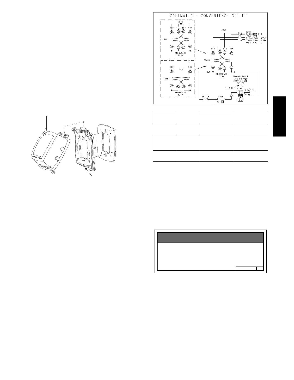
The primary l eads to the convenie nce outlet transformer
are not factory-- connected. Selection of primary power
source is a customer--option. If local codes permit, the
transformer primary leads can be connected at the
line--side terminals on the unit--mounted non--fused
disconnec t or HACR breaker switch; this will provide
service power to the unit when the unit disconnect switch
or HACR switch is open. Other connection methods will
result in the convenience outlet circuit being de--energized
when the unit disconnect or HACR switch is open. See
Fig. 22.
C08283
UNIT
VOLTAGE
CONNECT
AS
PRIMARY
CONNECTIONS
TRANSFORMER
TERMINALS
208,
230
240
L1: RED +YEL
L2: BLU + GRA
H1 + H3
H2 + H4
460 480
L1: RED
Splice BLU + YEL
L2: GRA
H1
H2 + H3
H4
575 600
L1: RED
L2: GRA
H1
H2
Fig. 22 -- Powered Convenience Outlet Wiring
Test the GFCI receptacle by pressing the TEST button on
the face of the receptacle to trip and open the receptacle.
Check for proper grounding wires and power line phasing
if the GFCI receptacle does not trip as required. Press the
RESET button to clear the tripped condition.
Fuse on power type: The factory fuse is a Bussman
“Fusetron” T--15, non--renewable screw--in (E dison ba se)
type plug fuse.
B50HJ542739
Maximum Continuous use : 8 Amps 24/7
Convenience Outlet Utilization
NOTICE
C13415
Fig. 23 -- Convenience Outlet Utilization Notice Label
Using unit--mounted convenience outlets: Units with
unit--mounted convenience outlet circuit s will oft en
require that two di sconnects be opened to de--energize al l
power to the unit. Treat all units as electrically energized
until the convenienc e outlet power is also checked and
de--energization is confirmed. Obse rve National Electrical
Code Article 210, Branch Circuits, for use of convenience
outlets.
50TC

 Loading...


