26
Supply Air Temperature (SAT) Sensor —
On FIOP--equipped 50TC unit, the unit is supplied with a
supply--air temperature (SAT) sensor (33ZCSENSAT).
This sensor is a tubular probe type, approx 6--inches (152
mm) in length. It is a nominal 10 --k ohm thermistor.
The SAT is factory--wired. The SAT probe is wire--tied to
the supply--air opening (on the hori zontal opening end) in
its shipping posit ion. Remove the sensor for installation.
Re--position the sensor in the flange of the supply--air
opening or in the supply air duct (as requi red by local
codes). Drill or punch a
1
/
2
--in. hole in the flange or duct.
Use two field --supplied, self--drilling screws to secure the
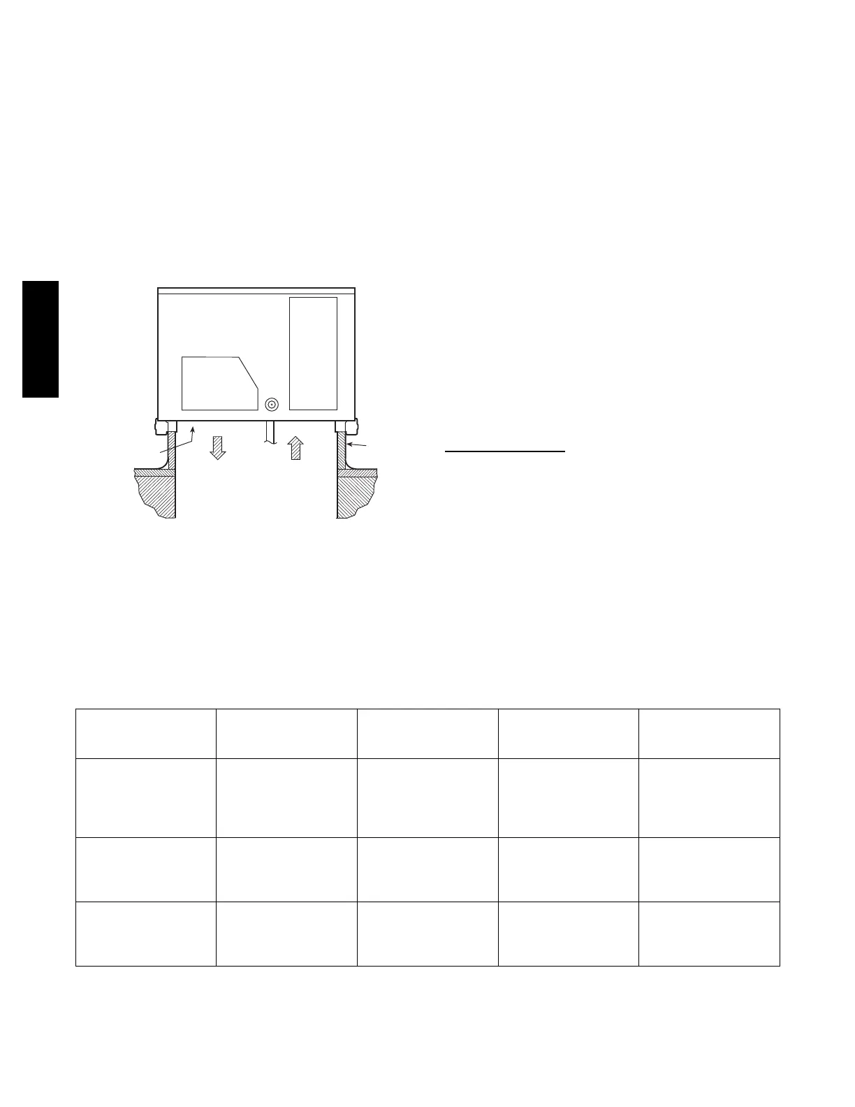
sensor probe in a horizontal orientation. See Fig. 41.
SUPPLY AIR
RETURN AIR
SUPPLY AIR
TEMPERATURE
SENSOR
ROOF
CURB
C08200
Fig. 41 -- Typical Mounting Location for Supply Air
Temperature (SAT) Sensor on Small Rooftop Units
NOTE: Refer to the PremierLinkt Controller Installation ,
Start--up, and Configuration Instructions for complete
PremierLink configuration, operating sequences and
troubleshooting information. Have a copy of this manual
available at unit start--up.
NOTE: The sensor must be mounted in the discharge
airstre am downstream of the cooling coil and any hea ting
devic es. Be sure the probe tip does not com e in contact
with any of the unit’s heater surfaces.
Outdoor Air Temperature (OAT) Sensor —
The OAT is factory--mounted in the EconoMi$er
R
2(FIOP
or accessory). It is a nominal 10k ohm thermistor attached
to an eyelet mounting ring.
EconoMi$e r2 —
The PremierLink controller is used with EconoMi$er2
(option or accessory) for outdoor air management. The
damper position is controlled directly by the PremierLink
controller; the EconoMi$er2 unit has no internal logic
devic e.
Outdoor air management functions can be enhanced with
field--installation of these accessory control devices:
Enthalpy cont rol (outdoor air or differential sensors)
Space CO
2
sensor
Outdoor air CO
2
sensor
Refer to Table 3 for accessory part numbers.
Field Connections
Field connections for accessory sensor and input devices
are made at the 16--pole terminal block (TB1) l ocated on
the control box bottom shelf in front of the PremierLink
control (See Fig. 39 and 40). Some input devices also
require a 24--vac signal source; connect at CTB terminal
R at “THERMOSTAT” connection strip for this signal
source. See connections figures on following pages for
field connection locations (and for continued connecti ons
at the PremierLink board inputs).
Table 4 provides a summary of field connections for units
equipped with Space Sensor. T able 5 provides a summary of
field connections for units equipped with Space Thermostat.
Table 3 – PremierLink Sensor Usage
APPLICATION
OUTDOOR AIR
TEMPERATURE
SENSOR
RETURN AIR
TEMPERATURE
SENSOR
OUTDOOR AIR
ENTHALPY SENSOR
RETURN AIR
ENTHALPY SENSOR
Differential Dry Bulb
Tempe rature w ith
PremierLink
(PremierLink requires
4 --- 2 0 m A A c t u a t o r )
I n c l u d e d ---
CRTEMPSN001A00
R e q u i r e d ---
33ZCT55SPT
or equivalent
--- ---
Single Enthalpy with
PremierLink
(PremierLink requires
4 --- 2 0 m A A c t u a t o r )
I n c l u d e d ---
Not Used
---
R e q u i r e s ---
33CSENTHSW
---
Differential Enthalpy
with PremierLink
(PremierLink requires
4 --- 2 0 m A A c t u a t o r )
I n c l u d e d ---
Not Used
---
R e q u i r e s ---
33CSENTHSW
R e q u i r e s ---
33CSENTSEN
NOTES:
CO
2
Sensors (Optional):
33ZCSENCO2 --- Room sensor (adjustable). Aspirator box is required for duct mounting of the sensor.
33ZCASPC O2 --- Aspirator box used for duct---mounted CO
2
room sensor.
33ZCT55CO2 --- Space temperature and CO
2
room sensor with override.
33ZCT56CO2 --- Space temperature and CO
2
room sensor with override and setpoint.
50TC

 Loading...


