37
Field Connections
Field connections for accessory sensors and input devices
are made the RTU Open controller, at plugs J1, J2, J4, J5,
J11 and J20. All field--control wiring that conne cts to the
RTU Open controller must be routed through the raceway
built into the corner post as shown in Fig. 26. The
raceway provides the UL required clearance between high
and low--voltage wiring. Pass the control wires through
the hole provided in the corner post, then feed the wires
thorough the raceway to the RTU Open controller.
Connect to the wires to the removable Phoenix connectors
and then rec onnect the connectors to the board.
Space Temperature (SPT) Sensors —
There are two types of SPT sensors ava ilable from Carrier,
resistive input non-communicating (T55, T56, and T59)
and Rnet communicating (SPS, SPPL, SPP, and SPPF)
sensors. Each type has a variety of options consisting of:
timed override button, set point adjustment, a LCD
screen, and communication tie in. Space temperature can
be also be written to from a building network or zoning
system. However, it is still recommended that return air
duct sensor be installed to allow stand-alone operation for
back-up. Refer to the configuration section for detail s on
controller configurations associated with space sensors.
S 33ZCT55SPT, space temperature sensor with override
button (T--55)
S 33ZCT56SPT, space temperature sensor with override
button and setpoint adjustment (T--56)
S 33ZCT59SPT, space temperature sensor with LCD
(liquid crystal display) screen, override button, and
setpoint adjustment (T--59)
Use 20 gauge wire to connect the sensor to the controller.
The wire is suitable for distances of up to 500 ft. Use a
three--conductor shielded cable for the sensor and setpoint
adjustment connections. If the setpoint adjustment
(slidebar) is not required, then an unshielded, 18 or 20
gauge, two--conductor, twisted pair cable may be used.
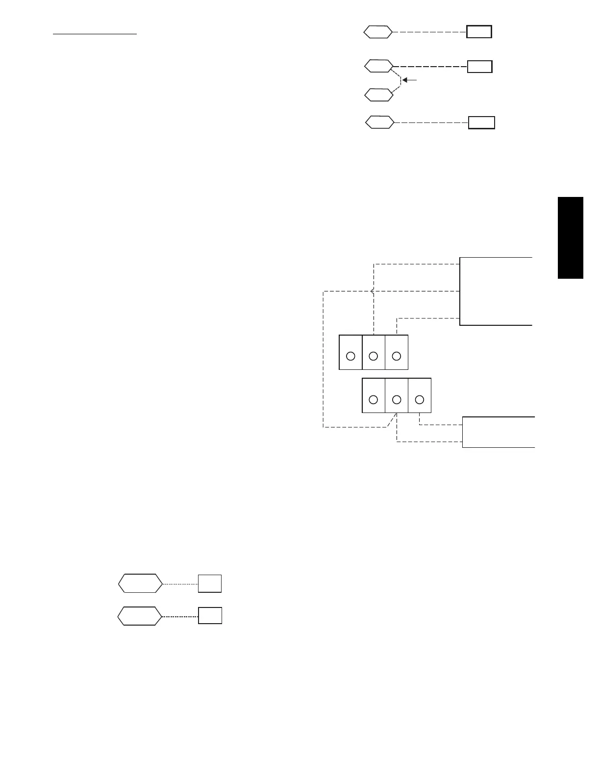
Connect T-- 55: See Fig. 42 for typical T--55 inte rnal
connec tions. Connect the T--55 SEN terminals to RTU
Open controller J20--1 and J20--2. See Fig. 61.
SEN
SEN
J20-1
J20-2
C08460
Fig. 61 -- RTU Open Controller T--55 Sensor
Connections
Connect T-- 56: See Fig. 44 for T--56 internal connections.
Install a jumper between SEN and SET terminals as
illustrated. Connect T--56 terminals to RTU Open
controller at J20--1, J20--2 and J20--3 per Fig. 62.
SEN J20-1
J20-2
SEN
SET
Jumper
J20-3
SET
C08461
Fig. 62 -- RTU Open Controller T--56 Sensor
Connections
Connect T--59: The T--59 space sensor requires a
separat e, isolated power supply of 24 VAC. See Fig. 63
for internal connections at the T--59. Connect the SEN
terminal (BLU) to the RTU Open controller at J20 --1.
Connect the COM t erminal (BRN) to J20--2. Connect the
SET terminal (STO or BLK) to J20--3.
OR SET SEN
OPB COM- PWR+
BLU (SPT)
BLK (STO)
24 VAC
SENSOR
WIRING
POWER
WIRING
BRN (COM)
NOTE: Must use a separate isolated transformer.
J20-3
J20-2
J20-1
C10291
Fig. 63 -- Space Temperature Sensor Typical Wiring
(33ZCT59SPT)
Indoor Air Quality (CO
2
)Sensor—
The i ndoor air quality sensor accessory monitors space
carbon dioxi de (CO
2
) levels. This information is used to
monitor IAQ levels. Several types of sensors are available,
for wall mounting in the space or in return duct, with and
without LCD display, and in combination with space
temperature sensors. Sensors use infrared technology to
mea sure the levels of CO
2
present in the space air.
The CO
2
sensors are all factory set for a range of 0 to
2000 ppm and a linear mA output of 4 to 20. Refer to the
instructions supplied with the CO
2
sensor for electrical
requirements and terminal locations. See Fig. 47 for
typical CO
2
sensor wiring schematic.
To accurately monitor the quality of the air in the
conditioned air space, locate the sensor near a return--air
grille (if present) so it senses the concentration of CO
2
leaving the space. The sensor should be mounted in a
location to avoid direct breath contact.
50TC

 Loading...


