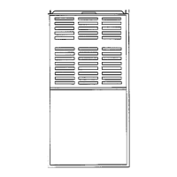
58GFA
Upflow Induced-Combustion Furnaces
Installation, Start-Up, and Operating Instructions
Sizes 065-150, Series 130
NOTE: Read the entire instruction manual before starting the
installation.
This symbol → indicates a change since the last issue.
Index Page
SAFETY CONSIDERATIONS ................................................. 1
INTRODUCTION ................................................................... 1-2
Clearance From Combustible Materials..................................1
Dimensional Drawing...............................................................2
LOCATION ..............................................................................2-3
General .................................................................................2-3
Location Relative to Cooling Equipment ................................3
Hazardous Locations.................................................................3
AIR FOR COMBUSTION AND VENTILATION...................3-4
Unconfined Space.....................................................................3
Confined Space......................................................................3-4
FILTER ARRANGEMENT .......................................................4-5
LEVELING LEGS ....................................................................5-6
GAS PIPING ................................................................................6
ELECTRICAL CONNECTIONS .............................................6-7
115-v Wiring ...........................................................................6
24-v Wiring...............................................................................7
Accessory ..................................................................................7
VENTING ....................................................................................7
START-UP, ADJUSTMENT, AND SAFETY CHECK.........7-13
Sequence Of Operation.............................................................8
Heating Mode............................................................................8
Cooling Mode ...........................................................................8
Continuous Blower Mode.........................................................8
Start-up Procedures..............................................................8-10
Adjustments .......................................................................10-12
Check Safety Controls.......................................................12-13
Checklist..................................................................................13
SAFETY CONSIDERATIONS
Installing and servicing heating equipment can be hazardous due to
gas and electrical components. Only trained and qualified person-
nel should install, repair, or service heating equipment.
Untrained personnel can perform basic maintenance functions
such as cleaning and replacing air filters. All other operations must
be performed by trained service personnel. When working on
heating equipment, observe precautions in the literature, on tags,
and on labels attached to or shipped with the unit and other safety
precautions that may apply.
Follow all safety codes. In the United States, follow all safety
codes including the National Fuel Gas Code NFPA No. 54-
1992/ANSI Z223.1-1992 (NFGC). In Canada, refer to the current
edition of the National Standard of Canada CAN/CGA-B149.1-
and .2-M95 Natural Gas and Propane Gas Installation Codes
(NSCNGPIC). Wear safety glasses and work gloves. Have fire
extinguisher available during start-up and adjustment procedures
and service calls.
Recognize safety information. This is the safety-alert symbol
.
When you see this symbol on the furnace and in instructions or
manuals, be alert to the potential for personal injury.
Understand the signal word DANGER, WARNING, or CAU-
TION. These words are used with the safety-alert symbol. DAN-
GER identifies the most serious hazards which will result in severe
personal injury or death. WARNING signifies a hazard which
could result in personal injury or death. CAUTION is used to
identify unsafe practices which would result in minor personal
injury or product and property damage.
NOTE is used to highlight suggestions which will result in
enhanced installation, reliability, or operation.
These instructions cover minimum requirements and conform to
existing national standards and safety codes. In some instances,
these instructions exceed certain local codes and ordinances,
especially those that may not have kept up with changing residen-
tial construction practices. We require these instructions as a
minimum for a safe installation.
INTRODUCTION
The model 58GFA Series 130 Furnaces are available in sizes
65,000 through 150,000 Btuh input capacities.
The design of the upflow gas-fired furnace is A.G.A./C.G.A.
certified for natural and propane gas and for installation on
combustible flooring, in alcoves, attics, basements, closets, or
utility rooms. The design of this furnace line is not A.G.A./C.G.A.
certified for installation in mobile homes, recreation vehicles, or
outdoors.
Table 1—Minimum Clearances From Combustible
Materials (In.)
UNIT SIZE 065 086-150
Sides Single-Wall Vent 1 0
Type B-1 Double-Wall Vent 0 0
Back 00
Top of Plenum 11
Vent Single-Wall Vent 6 6
Type B-1 Double-Wall Vent 1 1
Front Single-Wall Vent 6 6
Type B-1 Double-Wall Vent 3 3
Service 30 30
NOTES:
1. Provide 30-in. front clearance for servicing. An open door in front of the
furnace can meet this requirement.
2. A minimum clearance of 3 in. must be provided in front of the furnace for
combustion air and proper operation.
®
ama
CANADIAN GAS ASSOCIATION
APPROVED
R
Manufacturer reserves the right to discontinue, or change at any time, specifications or designs without notice and without incurring obligations.
Book 1 4
Tab 6a 8a
PC 101 Catalog No. 535-809 Printed in U.S.A. Form 58GF-4SI Pg 1 10-95 Replaces: 58GF-3SI
→