A bottom closure panel is factory installed in the bottom of the
furnace. When bottom return inlet is desired, remove and discard
the enclosure panel.
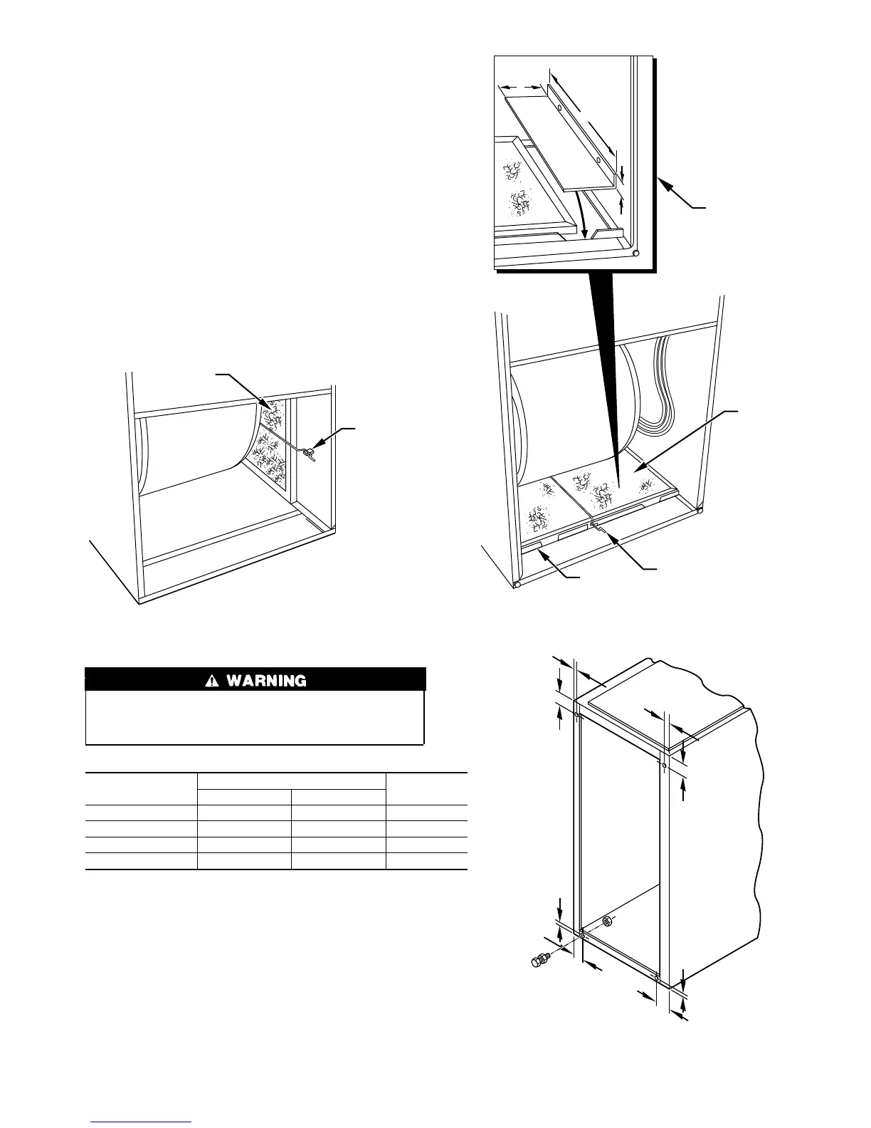
Filter retaining brackets, supports, and retainers are factory as-
sembled and shipped installed for side return application, with 1
set of all required hardware provided. (See Fig. 4.) For bottom
return applications, remove the brackets (front and back) and
supports from each side. The back bracket(s) are installed in the
rear of the furnace casing. Dimples are provided to mark mounting
screw locations.
The front bracket(s) are installed on the bottom front plate as
shown in Fig. 5, once the bottom enclosure has been removed.
Rotate filter supports 180° so filter will rest on support, and
reinstall. (Do not reinstall in 17-1/2 in. casing.) Install the filter
retaining rod (small U-shaped end) in the rear bracket, and the
front of the filter retainer rod as shown in Fig. 5. Two sets of
hardware are needed for furnaces in 24-1/2 in. casings using 1
filter for bottom return. All hardware is provided for filter
installation.
Never operate unit without a filter or with filter access door
removed. Failure to follow this warning can cause fire,
personal injury, or death.
Table 3—Filter Information (In.)
FURNACE CASING
WIDTH
FILTER QUANTITY AND SIZE*
FILTER TYPE
Side Return Bottom Return
14-3/16 (1) 16 X 25 X 1† (1) 14 X 25 X 1 Cleanable
17-1/2 (1) 16 X 25 X 1† (1) 16 X 25 X 1 Cleanable
21 (1) 16 X 25 X 1 (1) 20 X 25 X 1† Cleanable
24-1/2 (2) 16 X 25 X 1† (1) 24 X 25 X 1 Cleanable
* Filter can be field modified by cutting to the desired size. Alternate sizes can
be ordered from your distributor or dealer.
† Factory provided with the furnace.
Step 4—Leveling Legs (If Required)
When the furnace is used with side inlet(s) and leveling legs are
required, refer to Fig. 6, and install field-supplied, corrosion-
resistant 5/16-in. machine bolts and nuts.
NOTE: The maximum length of the bolt should not exceed 1-1/2
in.
1. Lay furnace on its back. Locate and drill 5/16-in. diameter
hole in each bottom corner of furnace as shown in Fig. 6.
2. Install nut on bolt and install bolt and nut in hole. (Install flat
washer if desired.)
Fig. 4—Side Filter Arrangement
A93045
FILTER
RETAINER
WASHABLE
FILTER
Fig. 5—Bottom Filter Arrangement
A93321
WASHABLE
FILTER
FILTER
SUPPORT
FILTER
RETAINER
FIELD-SUPPLIED
FILTER FILLER
STRIP FOR
17
1
⁄2-IN. WIDE
CASINGS ONLY.
INSTALL UNDER
FILTER.
1″
24
1
/
2
″
3″
Fig. 6—Leveling Leg Installation
A89014
1
3
⁄4″
1
3
⁄4″
1
3
⁄4″
1
3
⁄4″
5
⁄16″
5
⁄16″
5
⁄16″
5
⁄16″
5