If the furnace is installed on a raised platform to provide a return-
air plenum, and return air is taken directly from the hallway or
space adjacent to the furnace, all air for combustion must come
from outdoors.
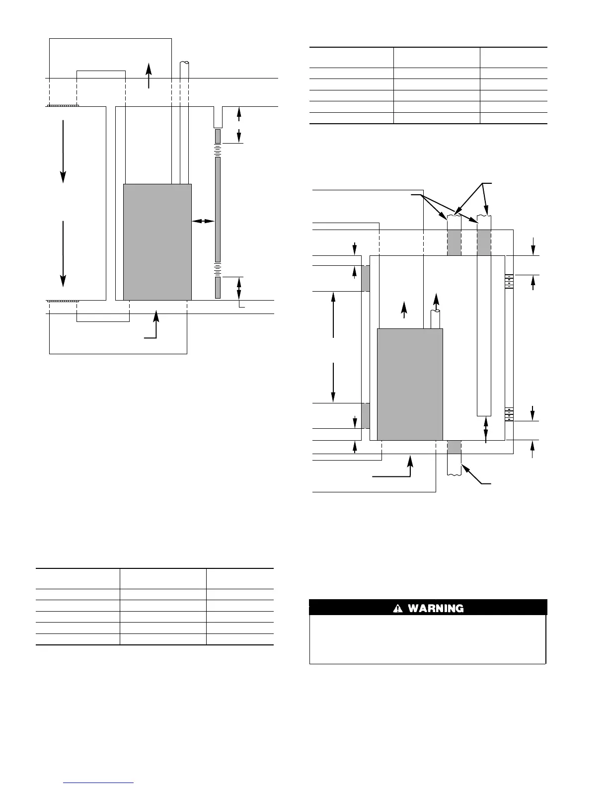
2. All air from outside the structure:
a. If combustion air is taken from outdoors through vertical
ducts, the openings and ducts MUST have at least 1 sq in.
of free area per 4000 Btuh of the total input for all
equipment within the confined space. (See Fig. 3.)
For Example:
58GFA FURNACE
INPUT BTUH
FREE AREA PER
OPENING (SQ IN.)
ROUND PIPE
(IN. DIA)
63,000 16.0 5
84,000 21.0 6
105,000 26.5 6
126,000 31.5 7
147,000 37.0 7
b. If combustion air is taken from the outdoors through
horizontal ducts, the openings and ducts MUST have at
least 1 sq in. of free area per 2000 Btuh of the total input
for all equipment within the confined space.
For Example:
58GFA FURNACE
INPUT BTUH
FREE AREA PER
OPENING (SQ IN.)
ROUND PIPE
(IN. DIA)
63,000 31.5 7
84,000 42.0 8
105,000 52.5 9
126,000 63.0 9
147,000 73.5 10
When ducts are used, they must be of the same cross-sectional area
as the free area of the openings to which they connect. The
minimum dimension of rectangular ducts must not be less than 3
in. (See Fig. 3.)
Do not install the furnace on its back; safety control operation
will be adversely affected. Never connect return-air ducts to
the back of the furnace. Failure to follow this warning can
cause a fire, personal injury, or death.
Step 3—Filter Arrangement
The factory-supplied filter(s) is shipped in the blower compart-
ment. Determine location for the filter and move filter retaining
hardware, if necessary, before attaching the return-air duct. After
the return-air duct has been connected to the furnace, install the
filter(s) inside the furnace blower compartment. See Fig. 4 for side
return application and Fig. 5 for bottom return application.
Fig. 2—Air for Combustion and Ventilation
(Inside Air)
A89012
SUPPLY
AIR
6″ MIN
(FRONT)
†
RETURN AIR
VENT THROUGH ROOF
1 SQ IN.
PER 1000
BTUH
*
IN DOOR
OR WALL
12″ MAX
1 SQ IN.
PER 1000
BTUH
*
IN DOOR
OR WALL
12″ MAX
INTERIOR
HEATED
SPACE
* Minimum opening size is 100 square in. with
minimum dimensions of 3-In.
†
Minimum of 3-In. when type-B1 vent is used.
UNCONFINED
SPACE
CONFINED
SPACE
Fig. 3—Air for Combustion and Ventilation
(Outside Air)
A89013
1 SQ IN.
PER
4000
BTUH*
DUCTS
TO
OUTDOORS
1 SQ IN.
PER 4000
BTUH*
SUPPLY
AIR
VENT
THROUGH
ROOF
D
B
A
C
E
1 SQ IN.
PER 4000
BTUH*
DUCT
TO
OUTDOORS
RETURN AIR
1 SQ IN.
PER 2000
BTUH*
1 SQ IN.
PER 2000
BTUH*
DUCTS
TO
OUTDOORS
12″ MAX
12
″ MAX
12″ MAX
Use any of the following
combinations of openings:
A & B C & D D & E F & G
NOTE:
*Minimum dimensions of 3-In.
CONFINED
SPACE
12″
MAX
12″
MAX
OUTDOORS
1 SQ IN.
PER
4000
BTUH*
F
G
4