10
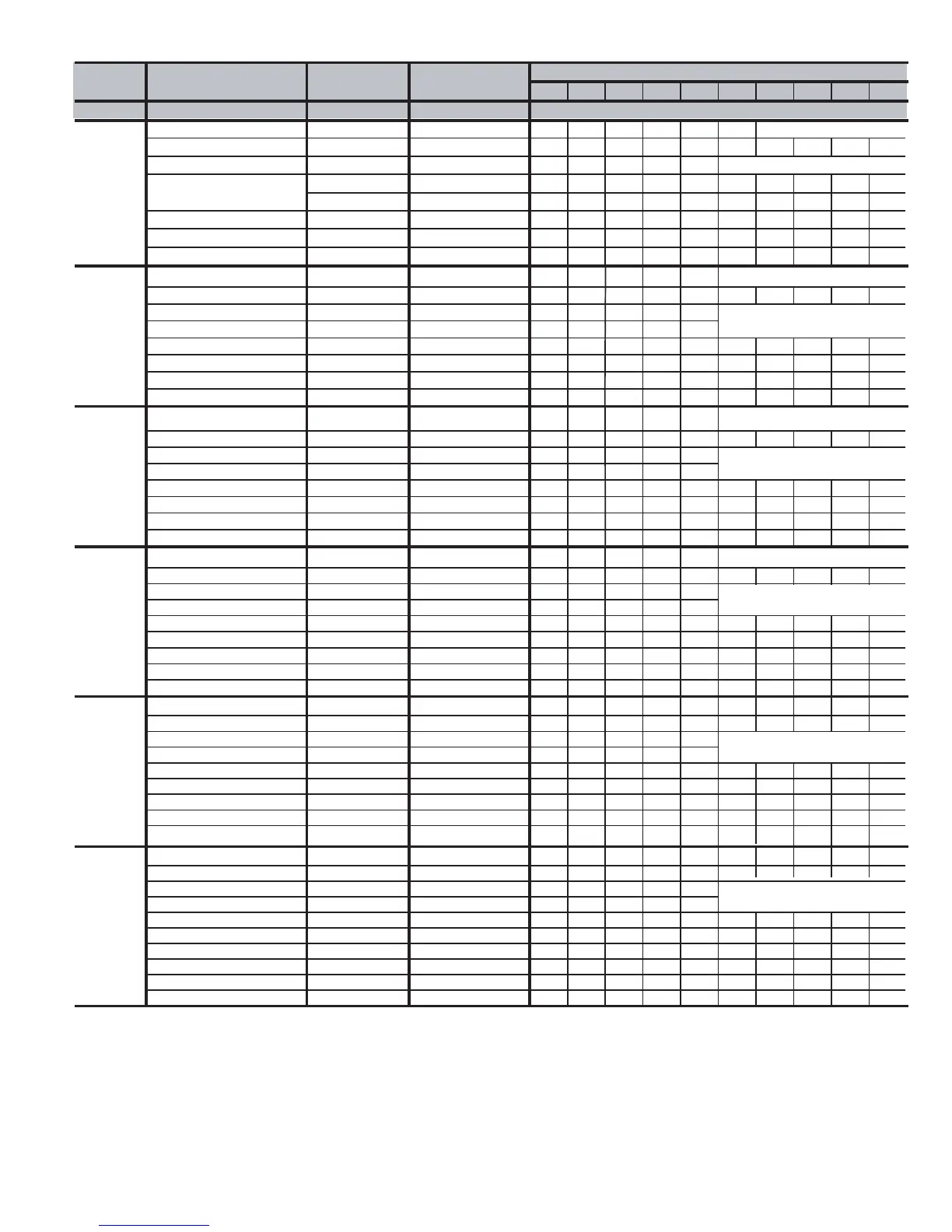
AIR DELIVERY - POWER DRAW (WATTS)**
Unit Operating Mode CFM Airflow External Static External Static Pressure (ESP)
Size Setting Pressure Range* 0.1 0.2 0.3 0.4 0.5 0.6 0.7 0.8 0.9 1.0
040-14
POWER DRAW (WATTS)**
††
Low Heat 585
†
0-0.60 55 71 91 108 129 147
High Heat 800 0-1.0 97 119 141 165 187 209 230 252 274 292
††
1-1/2-Ton Cooling 525 0-0.50
‡
49 63 75 94 107
††
2-Ton A/C Cooling 700 0-0.90
‡
67 92 117 134 159 186 216 239 267 296
2-1/2-Ton A/C Cooling 875 0-1.0 112 138 164 188 210 236 256 275 295 317
3-Ton A/C Cooling 1050 0-1.0 167 202 233 263 288 307 334 364 388 417
3-1/2-Ton A/C Cooling
1225 0-1.0 232 266 308 341 380 413 448 491 524 561
Maximum 1400 0-1.0 317 379 425 475 527 535 542 546 551 563
060-14
††
Low Heat 500
†
0-0.50 43 55 70 83 97
High Heat 1065 0-1.0 150 175 200 234 264 292 321 352 378 408
††
1-1/2-Ton A/C Cooling 525 0-0.50
‡
46 62 74 91 104
††
2-Ton A/C Cooling 700 0-0.50
‡
69 86 105 124 138
2-1/2-Ton A/C Cooling 875 0-1.0
‡
101 126 154 179 202 226 248 267 287 313
3-Ton A/C Cooling 1050 0-1.0 149 174 199 233 263 291 320 351 377 407
3-1/2-Ton A/C Cooling 1225 0-1.0 210 248 278 312 344 384 418 449 476 503
Maximum
1400 0-1.0 311 341 384 420 455 495 529 568 602 612
080-14***
††
Low Heat 720
†
0-0.50 80 95 118 142 168
High Heat 1500 0-1.0 442 507 519 527 535 543 550 557 564 572
††
1-1/2-Ton A/C Cooling 525 0-0.50
‡
50 63 80 96 111
††
2-Ton A/C Cooling 700 0-0.50
‡
73 94 113 133 156
2-1/2-Ton A/C Cooling 875 0-1.0
‡
102 133 161 191 218 241 268 291 320 348
3-Ton A/C Cooling 1050 0-1.0
‡
168 206 240 273 299 324 356 385 418 460
3-1/2-Ton A/C Cooling 1225 0-1.0
‡
245 277 317 355 394 431 481 522 558 568
Maximum 1400 0-1.0
‡
376 422 478 520 527 537 544 553 560 568
080-20***
††
Low Heat 705
†
0-0.50 76 90 112 129 149
High Heat 1500 0-1.0 381 432 478 511 564 610 650 688 732 761
††
2-Ton A/C Cooling 700 0-0.50
‡
76 89 109 127 148
††
2-1/2-Ton A/C Cooling 875 0-0.50
‡
113 136 157 178 208
3-Ton A/C Cooling 1050 0-1.0
‡
158 191 213 239 266 300 326 351 392 425
3-1/2-Ton A/C Cooling 1225 0-1.0
‡
227 262 294 322 360 390 432 459 501 538
4-Ton A/C Cooling 1400 0-1.0
‡
298 340 384 417 458 493 534 574 607 647
5-Ton A/C Cooling 1750 0-1.0 587 631 664 724 772 815 861 907 943 988
Maximum 2000 0-1.0 839 911 973 1029 1066 1104 1134 1149 1170 1182
100-20***
Low Heat 920
†
0-1.0 113 136 159 186 221 243 263 285 316 340
High Heat 1525 0-1.0 378 419 448 486 518 561 606 650 696 730
††
2-Ton A/C Cooling 700 0-0.50
‡
74 89 109 126 146
††
2-1/2-Ton A/C Cooling 875 0-0.50
‡
99 124 147 168 200
3-Ton A/C Cooling 1050 0-1.0
‡
144 177 207 229 258 288 319 350 385 415
3-1/2-Ton A/C Cooling 1225 0-1.0
‡
189 223 268 306 346 377 399 447 488 517
4-Ton A/C Cooling 1400 0-1.0
‡
283 328 360 400 439 474 510 541 575 598
5-Ton A/C Cooling 1750 0-1.0 502 558 602 657 715 754 797 847 889 930
Maximum 2000 0-1.0 766 819 887 947 991 1030 1065
1101
1129 1152
120-20
Low Heat 1180
†
0-1.0 162 194 228 265 297 325 363 392 432 459
High Heat 1885 0-1.0 547 607 652 715 756 816 870 912 958 1000
††
2-Ton A/C Cooling 700 0-0.50
‡
72 89 113 128 146
††
2-1/2-Ton A/C Cooling 875 0-0.50
‡
98 119 140 163 187
3-Ton A/C Cooling 1050 0-1.0
‡
126 156 194 221 249 279 307 327 351 381
3-1/2-Ton A/C Cooling 1225 0-1.0
‡
178 211 253 284 314 352 382 424 455 494
4-Ton A/C Cooling 1400 0-1.0
‡
257 310 348 388 421 458 488 528 557 591
5-Ton A/C Cooling 1750 0-1.0
‡
461 498 552 618 665 711 760 800 847 888
6-Ton A/C Cooling 2100 0-1.0 794 867 931 996 1042 1092 1135 1152 1124 1098
Maximum 2100 0-1.0 592 673 746 811 885 935 994 1026 1102 1129
*
Actual external static pressure (ESP) can be determined by using the fan laws (CFM
2
proportional to ESP); such as,
a system with 1750 CFM at 0.5 ESP would operate at high-heating airflow of 1500 CFM at 0.37 ESP and low-heating airflow
of 705 CFM at 0.08 ESP.
†
Low heat CFM when low-heat rise adjustment switch (SW1-3) and comfort/efficiency adjustment switch (SW1-4) on
control center are OFF.
‡
Ductwork must be sized for high-heating CFM within the operational range of ESP.
** Wattage data provided is for the circulating blower with bottom return and does not include draft inducer, accessories,
or gas controls.
††
Operation within the blank areas of the chart is not recommended because high-heat operation will be above 1.0 ESP.
*** All airflows on 21" casing size furnaces are 5% less on side return only installations.
 Loading...


