8
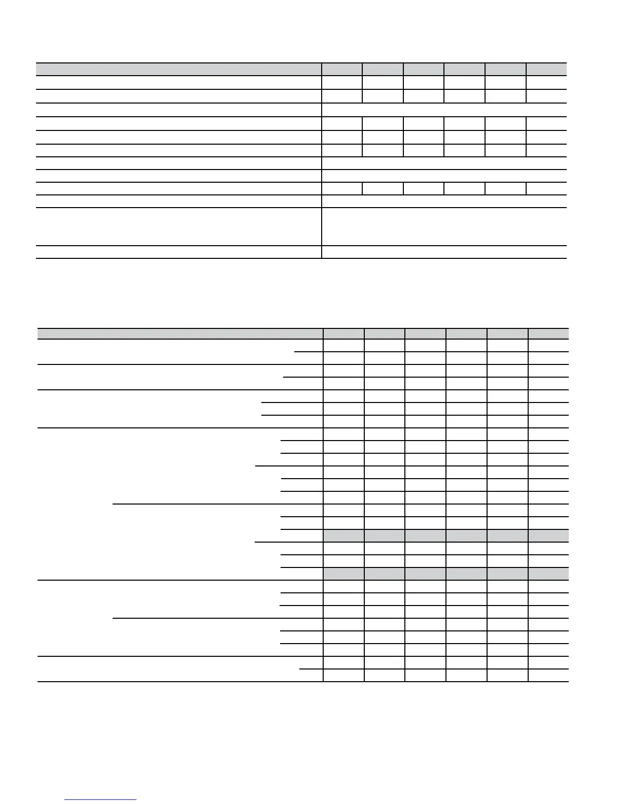
Physical data
UNIT SIZE 040-14 060-14 080-14 080-20 100-20 120-20
DIRECT-DRIVE MOTOR Hp (ECM)
1/2 1/2 1/2 1 1 1
MOTOR FULL LOAD AMPS
7.7 7.7 7.7 12.8 12.8 12.8
RPM (Nominal) — SPEEDS
Variable 250 — 1300
BLOWER WHEEL DIAMETER X WIDTH (In.)
11 x 10 10 x 7 11 x 10 11 x 10 11 x 10 11 x 10
FILTER SIZE (In.) NOMINAL A(Washable)
(1)24 x 25 x 1 (1)16 x 25 x 1 (1)20 x 25 x1 (1)20 x 25 x1 (1)20 x 25 x1 (1)24 x 25 x 1
SHIPPING WEIGHT (Lb) 205 170 182 204 203 234
LIMIT CONTROL SPST
HEATING BLOWER CONTROL (Off Delay) Selectable 90, 120, 150, or 180 Sec Intervals
BURNERS (Monoport) 234456
GAS CONNECTION SIZE 1/2-in. NPT
GAS VALVE (Redundant) Manufacturer White-Rodgers
Minimum Inlet Pressure (In. wc) 4.5 (Natural Gas)
Maximum Inlet Pressure (In. wc) 13.6 (Natural Gas)
IGNITION DEVICE Hot Surface
Performance data
* Capacity in accordance with U.S. Government DOE test procedures.
† Gas input ratings are certified for elevations to 2000 ft. For elevations above 2000 ft, reduce ratings 2% for each 1000 ft above sea level.
In Canada, derate the unit 5% for elevations from 2000 to 4500 ft above sea level.
‡ Airflow shown is for bottom only return-air supply with factory-supplied 1-in. washable filter(s). For air delivery above 1800 CFM, see Air Delivery
table for other options.
** Low heat CFM when low-heat rise adjustment switch (SW1-3) on furnace control is used.
UNIT SIZE 040-14 060-14 080-14 080-20 100-20 120-20
CERTIFIED TEMP RISE RANGE (°F) Low 25 — 55 50 — 80 50 — 80 50 — 80 50 — 80 50 — 80
High 30 — 60 35 — 65 35 — 65 35 — 65 45 — 75 45 — 75
CERTIFIED EXT STATIC PRESSURE (ESP) Heating 0.10 0.12 0.15 0.15 0.20 0.20
(In. wc) Cooling 0.50 0.50 0.50 0.50 0.50 0.50
AIRFLOW CFM‡ Heating Low
585(690**) 500 (590**) 720 (850**) 705 (830**) 920 (1085**) 1160 (1370**)
Heating High 800 1065 1500 1500 1525 1880
Cooling (Max) 1400 1500 1395 1990 2000 2100
OUTPUT CAPACITY
BTUH* (ICS)
(Shaded capacities
are specified on
rating plate)
Direct Vent (2-Pipe) Low Upflow 25,000 37,000 49,000 49,000 61,000 73,000
Downflow 25,000 36,000 49,000 49,000 61,000 73,000
Horizontal 25,000 36,000 49,000 49,000 61,000 73,000
High Upflow 38,000 57,000 75,000 75,000 94,000 113,000
Downflow 38,000 56,000 75,000 75,000 94,000 113,000
Horizontal 37,000 56,000 75,000 75,000 93,000 112,000
Non-Direct Vent (1-Pipe) Low Upflow 25,000 37,000 49,000 49,000 61,000 73,000
Downflow 25,000 36,000 49,000 49,000 61,000 73,000
Horizontal
25,000 36,000 49,000 49,000 61,000 73,000
High Upflow 38,000 57,000 75,000 75,000 94,000 113,000
Downflow 37,000 56,000 75,000 75,000 94,000 113,000
Horizontal
37,000 56,000 75,000 75,000 93,000 112,000
AFUE%*
Nonweatherized ICS
Direct Vent (2-Pipe) Upflow 96.6 94.1 94.1 94.1 94.1 94.1
Downflow
95 92.7 92.7 92.7 92.7 92.7
Horizontal 96.1 93.7 93.7 93.7 93.7 93.7
Non-Direct Vent (1-Pipe) Upflow 96.6 94.1 94.1 94.1 94.1 94.1
Downflow
95.0 92.7 92.7 92.7 92.7 92.7
Horizontal 96.1 93.7 93.7 93.7 93.7 93.7
INPUT BTUH† Low 26,000 39,000 52,000 52,000 65,000 78,000
High 40,000 60,000 80,000 80,000 100,000 120,000
 Loading...


