22
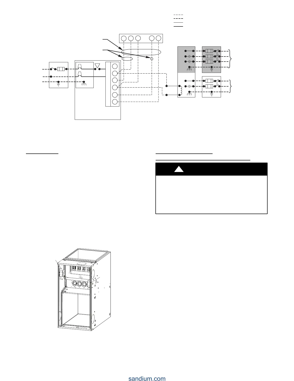
115-VOLT FIELD-
SUPPLIED
FUSED
DISCONNECT
JUNCTION
BOX
CONTROL
BOX
24-VOLT
TERMINAL
BLOCK
THREE-WIRE
HEATING-
ONLY
FIVE
WIRE
NOTE 2
NOTE 1
1-STAGE
THERMOSTAT
TERMINALS
FIELD-SUPPLIED
FUSED DISCONNECT
CONDENSING
UNIT
FURNACE
COM
R
WCY RG
GND
GND
FIELD 24-VOLT WIRING
FIELD 115-, 208/230-, 460-VOLT WIRING
FACTORY 24-VOLT WIRING
FACTORY 115-VOLT WIRING
Connect Y/Y2-terminal as shown for proper operation.
Some thermostats require a "C" terminal connection as shown.
If any of the original wire, as supplied, must be replaced, use
same type or equivalent wire.
208/230- OR
460-VOLT
THREE
PHASE
208/230-
VOLT
SINGLE
PHASE
WHT
BLK
WHT
BLK
W/W1
W2
Y/Y2
G
NOTES: 1.
2.
3.
A95236
Fig. 23 -- Field Wiring Diagram
J--Box Relocation
NOTE: If factory location of J--Box is acceptable, go to next
section (ELECTRICAL CONNECTION to J--Box).
NOTE: On 14 --in. (356 mm) wide casing models, the J--Box
shall not be relocated to other side of furnace casing when the
vent pipe is routed within the casing.
1. Remove and save two screws holding J-- Box. (See Fig.
24.)
NOTE: The J--Box cover need not be removed from the J--Box
in order to move the J -- Box. Do NOT remove green ground
screw inside J-- Box. (See Fig. 24.)
2. Cut wire tie on loop in furnace wires attached to J--Box.
3. Move J-- Box to desired location.
4. Fasten J--Box to casing with the two screws removed in
Step 1.
5. Route J--Box wires within furnace away from sharp edges,
rotating parts and hot surfaces.
FactoryFactory
InstalledInstalled
AlternateAlternate
LocationLocation
A10291
Fig. 24 -- Relocating J--Box
Electrical Connection to
J--Box
Electrical Box on Furnace Casing Side (See Fig. 25.)
FIRE OR ELECTRICAL SHOCK HAZARD
Failure to follow this warning could result in personal
injury, death, or property damage.
If field--supplied manual disconnect switch is to be mounted
on furnace casing side, select a location where a drill or
fastener cannot damage electrical or gas components.
!
WARNING
1. Select and remove a hole knockout in the casing where the
electrical box is to be installed.
NOTE: Check that duct on side of furnace will not interfere with
installed electrical box.
2. Remove the desired electrical box hole knockout and posi-
tion the hole in the electrical box over the hole in the fur-
nace casing.
3. Fasten the electrical box to casing by driving two field--
supplied screws from inside electrical box into casing
steel.
4. Remove and save two screws holding J-- Box. (See Fig.
24.)
5. Pull furnace power wires out of 1/2-- in. (12 mm) diameter
hole in J--Box. Do not loosen wires fro m strain--relief
wire-- tie on outside of J-- Box.
6. Route furnace power wires through holes in casing and
electrical box and into electrical box.
7. Pull field power wires into electrical box.
8. Remove cover from furnace J--Box.
9. Route field ground wire through holes in electrical box
and casing, and into furnace J-- Box.
10. Reattach furnace J--Box to furnace casing with screws re-
movedinStep4.
11. Secure field ground wire to J--Box green ground screw.
12. Complete electrical box wiring and installation. Connect
line voltage leads as shown in Fig. 25. Use best practices
(NEC in U.S. for wire bushings, strain relief, etc.