EasyManua.ls Logo

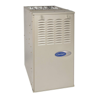
Carrier 58TMA - User Manual

Carrier 58TMA
18 pages
Print Icon
To Next Page IconTo Next Page
Loading...
58TMA
Downflow/Horizontal 2-Speed,
2-Stage Induced-Combustion Gas Furnace
Installation, Start-Up, and Operating Instructions
Series 100, Sizes 065-125
NOTE: Read the entire instruction manual before starting the
installation.
Index Page
SAFETY CONSIDERATIONS.....................................................1
Clearances to Combustibles......................................................1
ELECTROSTATIC DISCHARGE (ESD) PRECAUTIONS
PROCEDURE...........................................................................2
INTRODUCTION..........................................................................2
Dimensional Drawing ....................................................................3
LOCATION....................................................................................3
General ......................................................................................2
Location Relative to Cooling Equipment ................................3
Hazardous Locations.................................................................3
AIR FOR COMBUSTION AND VENTILATION...................3-5
Unconfined Space.....................................................................4
Confined Space......................................................................4-5
SUPPLY-AIR PLENUM INSTALLATION
(DOWNFLOW) ........................................................................5
Installation On a Concrete Slab ...............................................5
Installation On a Combustible Floor ....................................5-6
HORIZONTAL ATTIC INSTALLATION...................................6
HORIZONTAL CRAWLSPACE INSTALLATION....................6
FILTER ARRANGEMENT...........................................................6
GAS PIPING...............................................................................6-7
ELECTRICAL CONNECTIONS...............................................7-8
115-v Wiring..........................................................................7-8
24-v Wiring...............................................................................8
Accessories................................................................................8
VENTING ......................................................................................8
START-UP, ADJUSTMENT, AND SAFETY CHECK.........9-17
General.................................................................................9-10
Sequence of Operation ......................................................10-13
Adaptive Heating Mode ....................................................10-12
Non-Adaptive Heating Mode .................................................12
Cooling Mode....................................................................12-13
Continuous Blower Mode.......................................................13
Heat Pump Mode....................................................................13
Defrost Mode ..........................................................................13
Start-Up Procedures...........................................................13-17
Adjustments .......................................................................14-16
Set Gas Input Rate ............................................................14-15
Set Temperature Rise ........................................................15-16
Set Thermostat Heat Anticipator ......................................16-17
Check Safety Controls............................................................17
Checklist..................................................................................17
SAFETY CONSIDERATIONS
Installing and servicing heating equipment can be hazardous due to
gas and electrical components. Only trained and qualified person-
nel should install, repair, or service heating equipment.
Untrained personnel can perform basic maintenance functions
such as cleaning and replacing air filters. All other operations must
be performed by trained service personnel. When working on
heating equipment, observe precautions in the literature, on tags,
and on labels attached to or shipped with the unit and other safety
precautions that may apply.
Follow all safety codes. In the United States, refer to the National
Fuel Gas Code (NFGC) NFPA No. 54-1992/ANSI Z223.1-1992.
In Canada, refer to the current edition of the National Standard of
®
ama
CANADIAN GAS ASSOCIATION
A PP R O VED
R
Table 1— Clearances to Combustible
Materials (In.)
UNIT SIZE 065 AND 085 105 AND 125
DOWNFLOW (IN ALCOVE OR CLOSET)
Sides
Single-Wall Vent 1* 0
Type B-1 Double-Wall Vent 0 0
Back 0 0
Top 1 1
Front†
(See Notes)
Single-Wall Vent 6 6
Type B-1 Double-Wall Vent 3 3
Vent
Single-Wall Vent 6 6
Type B-1 Double-Wall Vent 1 1
HORIZONTAL POSITION (IN ALCOVE, ATTIC, AND
CRAWLSPACE)
Sides‡ 1 1
Back 0 0
Top
Single-Wall Vent 1 1
Type B-1 Double-Wall Vent 1 1
Front†
(See Notes)
Single-Wall Vent 6 6
Type B-1 Double-Wall Vent 3 3
Vent
Single-Wall Vent 6 6
Type B-1 Double-Wall Vent 1 1
HORIZONTAL POSITION (IN CLOSET)
Sides‡ ** 1 1
Back 3 3
Top
Single-Wall Vent 2 2
Type B-1 Double-Wall Vent 2 2
Front
(See Notes)
Single-Wall Vent 6 6
Type B-1 Double-Wall Vent 3 3
Vent
Single-Wall Vent 6 6
Type B-1 Double-Wall Vent 1 1
* For casing widths larger than 14-1/4 in., 0 clearance may be used.
18 in. front clearance required for alcove.
Clearance shown is for the outlet end. The inlet end must maintain 6 in.
clearance from flue to combustible materials when using single-wall vent.
** Indicates supply or return sides when furnace is in the horizontal position.
NOTES:
1. Provide 30-in. front clearance for servicing. An open door in front of the
furnace can meet this requirement.
2. A minimum clearance of 3 in. must be provided in front of the furnace for
combustion air and proper operation.
Manufacturer reserves the right to discontinue, or change at any time, specifications or designs without notice and without incurring obligations.
Book 1 4
Tab 6a 8a
PC 101 Catalog No. 535-824 Printed in U.S.A. Form 58TMA-3SI Pg 1 6/94 Replaces: 58TMA-2SI

Other manuals for Carrier 58TMA

Questions and Answers

  • C
    claytonpriceAug 15, 2025
    What to do if Carrier 58TMA Furnace is in gas heating lockout?
    • W
      Wendy DunnAug 15, 2025
      If your Carrier Furnace experiences a gas heating lockout, check for a mis-wired gas valve or a defective control (valve relay).

  • R
    Ronald JohnsonAug 18, 2025
    What to do if the limit or flame roll-out switch is open in Carrier 58TMA?
    • T
      theresa86Aug 18, 2025
      If the limit or flame roll-out switch is open in your Carrier Furnace, check for several potential issues: - Ensure there's an adequate supply of combustion air, especially for the FRS switch. - Inspect the filter and duct system for any dirt or restrictions. - Verify the blower wheel is securely in place. - Check the switch and its connections for defects. - Examine the blower motor and capacitor for any failures.
  • J
    Jessica LeblancAug 21, 2025
    How to fix ignition-proving fault in Carrier Furnace?
    • L
      Lori MillerAug 22, 2025
      If your Carrier Furnace displays an ignition-proving fault, consider the following checks: - Inspect the flame-proving sensor for oxide buildup and clean it gently with fine sandpaper. - Ensure the flame-proving microamps are at least 0.5. - Verify proper control ground continuity. - Confirm the flame-proving sensor is ungrounded. - Ensure smooth flame carryover and ignition. - Check that the manual valve(s) are not in the OFF position.
  • C
    crosscarlosAug 25, 2025
    What causes low-heat pressure, draft safeguard, or aux-limit switch not to close or reopen in Carrier 58TMA?
    • A
      Andrew WilsonAug 25, 2025
      If the low-heat pressure, draft safeguard, or auxiliary limit switch in your Carrier Furnace did not close or reopened, check the following: - Ensure proper vent sizing and condensate pitch, especially with side-wall vents. - Verify low inducer voltage (115v). - Inspect the blower motor and capacitor. - Check for a defective inducer motor. - Examine the pressure switch for defects. - Consider excessive wind conditions. - Look for a restricted vent. - Ensure an adequate combustion air supply. - Check for disconnected or obstructed pressure tubing.
  • N
    Nathan GoldenAug 28, 2025
    Why does the secondary voltage fuse keep opening in my Carrier 58TMA Furnace?
    • R
      Ryan MorrisAug 28, 2025
      If the secondary voltage fuse is open in your Carrier Furnace, check for a short-circuit in the secondary voltage (24V) wiring.
  • D
    daniel58Aug 31, 2025
    What causes high-heat pressure switch or relay not to close or reopen in Carrier 58TMA?
    • W
      wwalkerAug 31, 2025
      If the high-heat pressure switch or relay in your Carrier Furnace did not close or reopened, the control relay may be defective, so check it.
  • A
    Angelica RichSep 4, 2025
    What causes abnormal flame-proving signal in Carrier 58TMA Furnace?
    • E
      Edward LawsonSep 4, 2025
      If you are experiencing an abnormal flame-proving signal with your Carrier Furnace, check for a leaky or stuck-open gas valve.
  • C
    connie17Sep 7, 2025
    What to do if low-heat pressure, draft safeguard, or auxiliary limit switch open while high-heat pressure switch is closed in Carrier Furnace?
    • L
      Laura SchmidtSep 7, 2025
      If the low-heat pressure, draft safeguard, or auxiliary limit switch is open while the high-heat pressure switch is closed in your Carrier Furnace, check for disconnected or obstructed pressure tubing and a defective pressure switch (stuck open). Also, refer to #32 and #33.
  • J
    Jason HoodSep 12, 2025
    What causes low- or high-heat pressure switch not to open in Carrier 58TMA Furnace?
    • M
      Monica SinghSep 12, 2025
      If the low- or high-heat pressure switch did not open in your Carrier Furnace, check for obstructed pressure tubing or a defective pressure switch (stuck closed).

Summary

Safety Considerations

Clearances to Combustibles

Specifies minimum distances to combustible materials for safe installation.

Procedure

Air for Combustion and Ventilation

Unconfined Space

Air requirements for unconfined installation spaces based on furnace input.

Confined Space

Air requirements for confined installation spaces based on furnace input.

Gas Piping

Electrical Connections

Venting

Start-Up, Adjustment, and Safety Check

Sequence of Operation

Step-by-step process of furnace operation through various modes.

Cooling Mode

Heat Pump

Start-Up Procedures

Adjustments

Set Gas Input Rate

Procedure for setting the gas input rate for burners at high and low fire.

Set Temperature Rise

Procedure for setting the air temperature rise for heating modes.

Check Safety Controls

Checklist

Carrier 58TMA Specifications

General IconGeneral
BrandCarrier
Model58TMA
CategoryFurnace
LanguageEnglish

Related product manuals