EasyManua.ls Logo

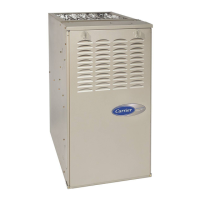
Carrier 58TP0A User Manual

Carrier 58TP0A
56 pages
To Next Page IconTo Next Page
Page #1 background imageLoading...
Page #1 background image
58TP0A/58TP1A
V a r i a b l e --- S p e e d , E C M
I n d u c e d --- C o m b u s t i o n , 2 --- S t a g e
4---Way Multipoise, Non---Condensing Gas Furnace
Series A
Installation, Start---up, Operating and
Se rvice and Maint e nance Inst ruct ions
SAFETY CONSIDERATIONS 3........................
INTRODUCTION 4..................................
CODES AND STANDARDS 4..........................
Safety 4...........................................
General Installation 4................................
Combustion and Ventilation Air 5......................
Duct Systems 5.....................................
Acoustical Lining and Fibrous Glass Duct 5...............
Gas Piping and Gas Pipe Pressure Testing 5...............
Electrical Connections 5..............................
Venting 5.........................................
ELECTROSTATIC DISCHARGE (ESD) PRECAUTIONS
PROCEDURE 5.....................................
LOCATION 6.......................................
AIR F OR COMBUSTION AND VENTILATION 7.........
Outdoor Combustion Air Method 7....................
The Standard Method: 8............................
Combination of Indoor and Outdoor Air 8..............
INSTALLATION 10..................................
Upflow Installation 10..............................
Downflow/Horizontal Installation 10..................
Leveling Legs (If Desired) 10........................
Suspended Furnace Support 11.......................
Platform Furnace Support 11.........................
Roll--Out Protection 12.............................
Bottom Return Air Inlet 11..........................
Side Return Air Inlet 11.............................
Filter Arrangement 11..............................
AIR DUCTS 12......................................
Ductwork Acoustical Treatment 12....................
Supply Air Connections 12..........................
Upflow and Horizontal Furnaces 12...................
Downflow Furnaces 13.............................
Return Air Connections 19..........................
Downflow Furnaces 19.............................
Upflow and Horizontal Furnaces 19...................
GAS PIPING 19.....................................
ELECTRICAL CONNECTION 21.......................
ACCESSORIES 23...................................
VENTING 24.......................................
START --UP, ADJUSTMENT, AND SAFETY CHECK 34.....
Start--Up Procedures 35..............................
Adjustments 37.....................................
Wiring Diagram 40..................................
Check Safety Controls 47.............................
Checklist 44.......................................
SERVICE AND MAINTENANCE PROCEDURES 44.......
General 45........................................
Care and Maintenance 46.............................
Sequence of Operation 49.............................
Troubleshooting 53..................................
PARTS REPLACEMENT INFORMATION GUIDE 55.......
NOTE: Read the entire instruction manual before starting the
installation.
Portions of the text and tables are reprinted from NFPA 54/ANSI
Z223.1E, with permission of National Fire Protection
Association, Quincy, MA 02269 and American Gas Association,
Washington DC 20001. This reprinted material is not the
complete and official position of the NFPA or ANSI on the
referenced subject, which is represented only by the standard in
its entirety.
sandium.com

Questions and Answers:

Carrier 58TP0A Specifications

General IconGeneral
BrandCarrier
Model58TP0A
CategoryFurnace
LanguageEnglish

Summary

SAFETY CONSIDERATIONS

WARNING FIRE, EXPLOSION, ELECTRICAL SHOCK, AND CARBON MONOXIDE POISONING HAZARD

Hazards associated with improper installation, adjustment, alteration, service, maintenance, or use.

CAUTION FURNACE RELIABILITY HAZARD

Hazards related to unit component damage due to improper application or installation.

CUT HAZARD

Personal injury risk from sharp sheet metal edges or burrs.

Safety Precautions

General safety instructions for installation and service.

General Installation Requirements

Specific requirements for installation, combustion, ventilation, and venting.

INSTALLATION

MINIMUM INCHES CLEARANCE TO COMBUSTIBLE CONSTRUCTION

Required clearances for furnace installation near combustible materials.

CODES AND STANDARDS

Compliance requirements with national and local codes.

INTRODUCTION

Overview of the furnace type and its certifications.

ELECTROSTATIC DISCHARGE (ESD) PRECAUTIONS PROCEDURE

CAUTION FURNACE RELIABILITY HAZARD

Precautions to prevent damage to electronic components from static discharge.

LOCATION

Notes on high-altitude installation and multipoise orientations.

WARNING FIRE, EXPLOSION, AND CARBON MONOXIDE POISONING HAZARD

WARNING CARBON MONOXOXIDE POISONING / COMPONENT DAMAGE HAZARD

Risks of corrosive air affecting furnace parts and living space.

WARNING FIRE, INJURY OR DEATH HAZARD

Hazards when installing furnace in garages or hazardous atmospheres.

WARNING FIRE HAZARD

Warning against installing furnace on its back or hanging it downwards.

LOCATION RELATIVE TO COOLING EQUIPMENT

Guidelines for installing cooling coils with the furnace.

AIR FOR COMBUSTION AND VENTILATION

CAUTION FURNACE CORROSION HAZARD

Hazards of contaminated air causing corrosion.

WARNING CARBON MONOXIDE POISONING HAZARD

Hazards from negative pressure conditions created by exhaust fans.

Outdoor Combustion Air Method

Method for providing combustion air from outdoors.

Indoor Combustion Air NFPA & AGA Standard and Known-Air-Infiltration Rate Methods

WARNING CARBON MONOXIDE POISONING HAZARD

Importance of supplying outdoor air for furnace combustion.

The Standard Method:

The Known Air Infiltration Rate Method

Method for determining air requirements when infiltration rate is known.

Combination of Indoor and Outdoor Air

Requirements for systems using both indoor and outdoor air.

INSTALLATION

UPFLOW INSTALLATION

Instructions for upflow installation configurations.

Leveling Legs (If Desired)

Instructions for installing leveling legs.

DOWNFLOW INSTALLATION

Approvals and requirements for downflow installations.

HORIZONTAL INSTALLATION

General notes on horizontal installation.

Suspended Furnace Support

Platform Furnace Support

Requirements for constructing a platform for furnace support.

Roll-Out Protection

Requirements for flame roll-out protection.

Bottom Return Air Inlet

Procedures for removing the bottom closure panel for bottom return air.

Filter Arrangement

WARNING CARBON MONOXIDE POISONING HAZARD

Hazards of operating without a filter or with the door removed.

AIR DUCTS

General requirements for duct system design and installation.

Downflow Furnaces

Fig. 14 - Duct Flanges

Illustration of duct flange configurations for different furnace orientations.

Fig. 15 - Horizontal Unit Suspension

Diagram showing methods for horizontal unit suspension.

VENTING NOTES FOR FIG. 36 - 48

Return Air Connections

WARNING FIRE HAZARD

Warning against connecting return-air ducts to the back of the furnace.

Downflow Furnaces

Requirements for connecting return air ducts for downflow furnaces.

Upflow and Horizontal Furnaces

Requirements for connecting return air ducts for upflow/horizontal furnaces.

GAS PIPING

WARNING FIRE OR EXPLOSION HAZARD

Hazards related to purging gas lines or testing for leaks.

ELECTRICAL CONNECTIONS

WARNING ELECTRICAL SHOCK, FIRE OR EXPLOSION HAZARD

Hazards of improper servicing and wiring.

WARNING ELECTRICAL SHOCK HAZARD

Hazards of bypassing the blower access door switch.

CAUTION FURNACE MAY NOT OPERATE HAZARD

Importance of proper control grounding.

J-Box Relocation

Electrical Connection to J-Box

Instructions for connecting the electrical box to the furnace.

Power Cord Installation in Furnace J-Box

BX Cable Installation in Furnace J-Box

Instructions for installing BX cable in the J-Box.

24-V Wiring

Instructions for making field 24-v connections.

ACCESSORIES

Information on connecting accessories like EAC and humidifier.

VENTING

General Venting Requirements

Safety codes and requirements for vent sizing and installation.

WARNING CARBON MONOXIDE POISONING HAZARD

Hazards of bypassing the draft safeguard switch.

Fig. 27 - Two-Stage Furnace with Single-Speed Air Conditioner

NOTES FOR FIGURES 27 - 34

CHIMNEY INSPECTION CHART

Masonry Chimney Requirement

Appliance Application Requirements

Factors affecting venting system performance.

CAUTION BURN HAZARD

Hazard of hot vent pipe near children.

Additional Venting Requirements

CAUTION CUT HAZARD

Personal injury risk from sharp sheet metal.

Fig. 36 - Upflow Application - Vent Elbow Up

Fig. 40 - Downflow Application - Vent Elbow Left then Up

Fig. 45 - Horizontal Left Application - Vent Elbow Up

Fig. 38 - Downflow Application - Vent Elbow Up then Left

Fig. 42 - Horizontal Left Application - Vent Elbow Left

VENTING NOTES FOR FIG. 36 - 48

START-UP, ADJUSTMENT, AND SAFETY CHECK

General

General notes on startup procedures.

WARNING FIRE HAZARD

Hazards related to limit switches and overheating.

CAUTION CUT HAZARD

Personal injury risk from sharp sheet metal.

Start-Up Procedures

WARNING FIRE OR EXPLOSION HAZARD

Hazards of purging gas lines or testing for leaks.

WARNING ELECTRICAL SHOCK HAZARD

Hazards related to the blower access door switch.

DIP SWITCH CONFIGURATION

SW1

Detailed description of SW1 dip switch functions.

SW2

Detailed description of SW2 dip switch functions.

LED CODE

SERVICE

Procedures for accessing service information and clearing codes.

Adjustments

Procedures for adjusting furnace settings.

EXAMPLE 1: 0-2000 ft. (0-610 M) altitude

CAUTION FURNACE DAMAGE HAZARD

Warning against improper adjustment of manifold pressure.

CAUTION UNIT DAMAGE HAZARD

Warning regarding reduced furnace life due to overheating.

CAUTION

FURNACE OVERHEATING HAZARD

Warning about reduced furnace life due to overheating.

Fig. 55 - Wiring Diagram

Table 10 - Gas Rate (CU ft./hr)

Table 11 - Orifice Size and Manifold Pressure (In. W.C.) for Gas Input Rate

Table 11 - Orifice Size and Manifold Pressure (In. W.C.) for Gas Input Rate (Con't.)

Check Safety Controls

1. Check Main Limit Switch

Testing the main limit switch function.

2. Check draft safeguard switch.

Testing the draft safeguard switch function.

3. Check Pressure Switch(es)

Testing the draft inducer blower pressure switch.

Checklist

Final checks before leaving the installation.

SERVICE AND MAINTENANCE PROCEDURES

General information on service and maintenance.

CAUTION ELECTRICAL OPERATION HAZARD

General

General notes on furnace orientation and controls.

Electrical Controls and Wiring

Information on electrical controls and wiring.

CARE AND MAINTENANCE

WARNING FIRE OR EXPLOSION HAZARD

Hazards of storing items near the furnace.

WARNING ELECTRICAL SHOCK AND FIRE HAZARD

Safety steps before performing maintenance.

WARNING CARBON MONOXIDE POISONING AND FIRE HAZARD

Warning about operating without a filter.

CAUTION CUT HAZARD

Personal injury risk from sharp sheet metal.

Cleaning and/or Replacing Air Filter

Procedures for cleaning or replacing the air filter.

Blower Motor and Wheel

Maintenance procedures for the blower motor and wheel.

Cleaning Heat Exchanger

Fig. 56 - Igniter Position - Side View

Sequence of Operation

WARNING FIRE OR EXPLOSION HAZARD

Hazards of purging gas lines or testing for leaks.

1. Two-Stage Heating (Adaptive Mode) with Single-Stage Thermostat

Operation for two-stage heating with a single-stage thermostat.

e. Blower-On delay

f. Switching from Low- to High-Heat

Transition process from low-heat to high-heat operation.

g. Switching from High- to Low-Heat

Transition process from high-heat to low-heat operation.

h. Blower-Off Delay

Blower operation after thermostat is satisfied.

2. Two-Stage Thermostat and Two-Stage Heating

Operation with a two-stage thermostat for heating.

3. Cooling mode

Furnace operation during cooling cycles.

4. Thermidistat Mode

Furnace operation with a Thermidistat.

5. Continuous Blower Mode

Furnace operation in continuous blower mode.

Continuous Blower Speed Selection from Thermostat

NOTE: If the blower-off delay is set to the maximum...

Note on blower speed adjustment limitation.

6. Heat pump

7. Component test

Procedure for initiating the component test.

Troubleshooting Guide – Variable Speed

Fig. 59 - Troubleshooting Guide (Continued)

PARTS REPLACEMENT INFORMATION GUIDE

CASING GROUP

List of casing components.

ELECTRICAL GROUP

List of electrical components.

BLOWER GROUP

List of blower components.

GAS CONTROL GROUP

List of gas control components.

HEAT EXCHANGER GROUP

List of heat exchanger components.

INDUCER GROUP

List of inducer components.

TO OBTAIN INFORMATION ON PARTS:

Contact information for ordering parts.

Example of Model Number

Explanation of furnace model number breakdown.

WARNING: Improper installation...

Warning about improper installation and use of parts.

Related product manuals