Installation, Start-up, Operating and
Service and Maintenance Instructions
NOTE: Read the entire instruction manual before starting the
installation.
TABLE OF CONTENTS
Table 1 – Dimensions . . . . . . . . . . . . . . . . . . . . . . . . . . . . . . . . . . 2
SAFETY CONSIDERATIONS . . . . . . . . . . . . . . . . . . . . . . . . . . . . . 3
INTRODUCTION . . . . . . . . . . . . . . . . . . . . . . . . . . . . . . . . . . . . . . . 4
LOCATION . . . . . . . . . . . . . . . . . . . . . . . . . . . . . . . . . . . . . . . . . . . . 6
Table 2 – Minimum Free Area Required for Each Combustion Air
opening of Duct to Outdoors . . . . . . . . . . . . . . . . . . . . . . . . . . . . . 8
Table 3 – Minimum Space Volumes for 100% Combustion, Ventila-
tion, and Dilution from Indoors . . . . . . . . . . . . . . . . . . . . . . . . . . . 9
INSTALLATION . . . . . . . . . . . . . . . . . . . . . . . . . . . . . . . . . . . . . . . . 9
Table 4 – Opening Dimensions - In. (mm) . . . . . . . . . . . . . . . . . 11
FILTER ARRANGMENT . . . . . . . . . . . . . . . . . . . . . . . . . . . . . . . . 13
AIR DUCTS . . . . . . . . . . . . . . . . . . . . . . . . . . . . . . . . . . . . . . . . . . . 13
GAS PIPING. . . . . . . . . . . . . . . . . . . . . . . . . . . . . . . . . . . . . . . . . . . 14
Table 5 – Maximum Capacity of Pipe . . . . . . . . . . . . . . . . . . . . . 14
ELECTRICAL CONNECTIONS. . . . . . . . . . . . . . . . . . . . . . . . . . . 15
Table 6 – Electrical Data . . . . . . . . . . . . . . . . . . . . . . . . . . . . . . . 16
INTELISENSE™ TECHNOLOGY . . . . . . . . . . . . . . . . . . . . . . . . . 18
ACCESSORIES . . . . . . . . . . . . . . . . . . . . . . . . . . . . . . . . . . . . . . . . 18
VENTING. . . . . . . . . . . . . . . . . . . . . . . . . . . . . . . . . . . . . . . . . . . . . 20
Table 7 – Combined Appliance Maximum Input Rating
in Thousands of BTUh per Hour . . . . . . . . . . . . . . . . . . . . . . . . . 21
Table 8 – Minimum Allowable Input Rating of
Space-Heating Appliance in Thousands of BTUh per Hour . . . . 21
Table 9 – Recommended Minimum Vent Height Per Furnace and Vent
Orientation . . . . . . . . . . . . . . . . . . . . . . . . . . . . . . . . . . . . . . . . . . 23
AIR DELIVERY - CFM. . . . . . . . . . . . . . . . . . . . . . . . . . . . . . . . . . 26
Table 10 – Air Delivery - CFM (with Filter)* . . . . . . . . . . . . . . . 26
Table 11 – Default Airflow Settings . . . . . . . . . . . . . . . . . . . . . . 29
FURNACE CONTROL PROGRAMMING
AND NAVIGATION . . . . . . . . . . . . . . . . . . . . . . . . . . . . . . . . . . . . 29
Table 12 – System Status Display Codes. . . . . . . . . . . . . . . . . . . 30
Table 13 – Main Menu Options . . . . . . . . . . . . . . . . . . . . . . . . . . 30
SERVICE LABEL . . . . . . . . . . . . . . . . . . . . . . . . . . . . . . . . . . . . . . 32
START-UP, ADJUSTMENT, AND SAFETY CHECK . . . . . . . . . 32
Table 14 – Test Sequence . . . . . . . . . . . . . . . . . . . . . . . . . . . . . . 33
WIRING DIAGRAM . . . . . . . . . . . . . . . . . . . . . . . . . . . . . . . . . . . . 33
ADJUSTMENTS . . . . . . . . . . . . . . . . . . . . . . . . . . . . . . . . . . . . . . . 34
Table 15 – Altitude Derate Multiplier for U.S.A. . . . . . . . . . . . . 34
Table 16 – Gas Rate (CU ft./hr). . . . . . . . . . . . . . . . . . . . . . . . . . 35
Table 17 – Orifice Size and Manifold Pressure (in. w.c.) for Gas Input
Rate (Tabulated Data Based on 22,000 BTUh High-Heat/14,500
BTUh for Low-Heat per Burner, Derated 4 Percent for Each 1000
Ft.(305 M) Above Sea Level) . . . . . . . . . . . . . . . . . . . . . . . . . . . 36
Table 18 – Orifice Size and Manifold Pressure (in. w.c.) for Gas Input
Rate (Tabulated Data Based on 21,000 BTUh High-Heat/14,500
BTUh for Low-Heat per Burner, Derated 4 Percent for Each 1000
Ft.(305 M) Above Sea Level) . . . . . . . . . . . . . . . . . . . . . . . . . . . 37
SERVICE AND MAINTENANCE PROCEDURES. . . . . . . . . . . . 40
CARE AND MAINTENANCE . . . . . . . . . . . . . . . . . . . . . . . . . . . . 41
Table 19 – Filter Size Information - In. (mm) . . . . . . . . . . . . . . . 42
Table 20 – Filter Size Information - In. (mm) . . . . . . . . . . . . . . . 42
SEQUENCE OF OPERATION . . . . . . . . . . . . . . . . . . . . . . . . . . . . 44
TROUBLESHOOTING GUIDE . . . . . . . . . . . . . . . . . . . . . . . . . . . 48
GAS FURNACE CHECKLIST . . . . . . . . . . . . . . . . . . . . . . . . . . . . 51
PARTS REPLACEMENT INFORMATION GUIDE . . . . . . . . . . . 52
MODEL NOMENCLATURE . . . . . . . . . . . . . . . . . . . . . . . . . . . . . 52
TRAINING. . . . . . . . . . . . . . . . . . . . . . . . . . . . . . . . . . . . . . . . . . . . 52
To learn more about this appliance and installation via a mobile device,
go to https://carrier.hvacpartners.com/NFC or use the QR code below.
To access airflow tables or troubleshooting guide on your mobile device
go to mlctraining.com/training/techdocs/74/ or use the QR code below.
To learn more about InteliSense, go to Carrier.hvacpartners.com/InteliSense
or use the QR code below.
A230214
A200103
Portions of the text and tables are reprinted from NFPA 54/ANSI Z223.1E, with permission of National Fire Protection Association, Quincy, MA
02269 and American Gas Association, Washington DC 20001. This reprinted material is not the complete and official position of the NFPA or ANSI
on the referenced subject, which is represented only by the standard in its entirety.
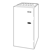
58TP0B/58TP1B
80% AFUE, Variable 25-Speed, ECM Motor,
Two-Stage, 4-Way Multipoise,
Non-Condensing Gas Furnace with InteliSense™


