58TP0B/58TP1B: Installation, Start-up, Operating and Service and Maintenance Instructions
Manufacturer reserves the right to change, at any time, specifications and designs without notice and without obligations.
16
115-V Wiring
Verify that the voltage, frequency, and phase correspond to that specified
on unit rating plate. Also, check to be sure that service provided by
utility is sufficient to handle load imposed by this equipment. Refer to
rating plate or Table 6 for equipment electrical specifications.
U.S. Installations: Make all electrical connections in accordance with
National Electrical Code (NEC) NFPA 70 and any local codes or
ordinances that might apply.
Use a separate, fused branch electrical circuit with a properly sized fuse
or circuit breaker for this furnace. See Table 6 for wire size and fuse
specifications. A readily accessible means of electrical disconnect must
be located within sight of the furnace.
NOTE: Proper polarity must be maintained for 115-V wiring. If polarity
is incorrect, control LED status indicator light will flash rapidly and
Status code (10.1) is displayed. The furnace will NOT operate.
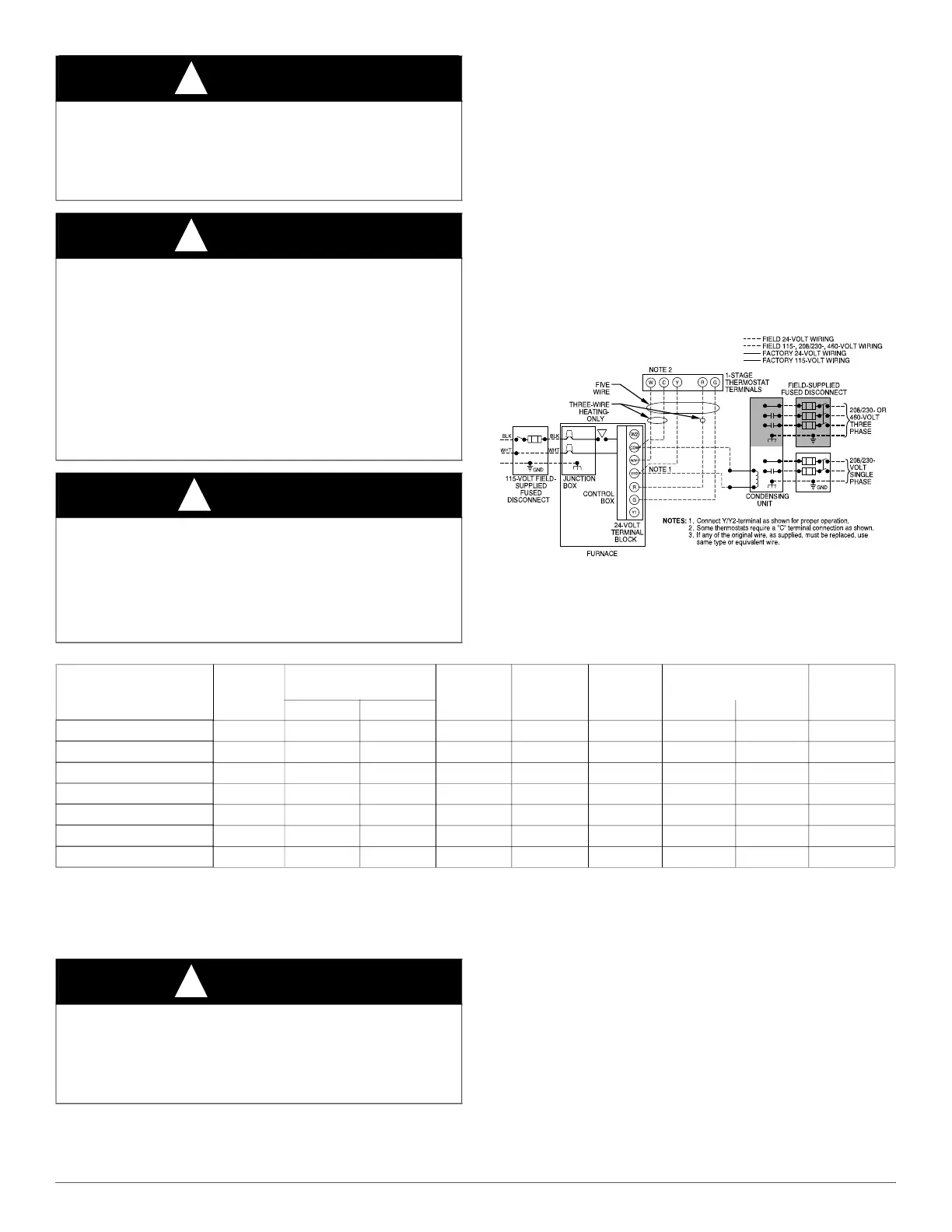
A230059
Fig. 24 – Typical Field Wiring Diagram
WARNING
!
ELECTRICAL SHOCK HAZARD
Failure to follow this warning could result in personal injury or death.
Blower access panel door switch opens 115-V power to control. No
component operation can occur. Do not bypass or close switch with
panel removed.
WARNING
!
ELECTRICAL SHOCK AND FIRE HAZARD
Failure to follow this warning could result in personal injury, death, or
property damage.
The cabinet MUST have an uninterrupted or unbroken ground
according to NEC NFPA 70 or local codes to minimize personal injury
if an electrical fault should occur. This may consist of electrical wire,
conduit approved for electrical ground or a listed, grounded power cord
(where permitted by local code) when installed in accordance with
existing electrical codes. Refer to the power cord manufacturer’s
ratings for proper wire gauge. Do not use gas piping as an electrical
ground.
CAUTION
!
FURNACE MAY NOT OPERATE HAZARD
Failure to follow this caution may result in intermittent furnace
operation.
Furnace control must be grounded for proper operation or else control
will lock out. Control must remain grounded through green/yellow wire
routed to gas valve and manifold bracket screw.
Table 6 – Electrical Data
FURNACE SIZE
VOLTS -
HERTZ -
PHASE
OPERATING VOLTAGE
RANGE
*
*. Permissible limits of the voltage range at which the unit operates satisfactorily.
MAX. UNIT
AMPS
UNIT
AMPACITY
†
†. Unit ampacity = 125 percent of largest operating component’s full load amps plus 100 percent of all other potential operating components’ (EAC,
humidifier, etc.) full load amps.
MIN WIRE
SIZE AWG
MAX WIRE LENGTH
FT (M)
‡
‡. Time-delay type is recommended.
MAX. FUSE
OR CKT. BKR
AMPS
**
**. Length shown is as measured 1 way along wire path between furnace and service panel for maximum 2 percent voltage drop.
Max. Min. Feet Meters
045V14--12 115-60-1 127 104 8.0 10.8 14 34 10.5 15
070V14--12 115-60-1 127 104 8.0 10.8 14 34 10.5 15
070V17--16 115-60-1 127 104 10.5 13.9 14 26 8.1 15
090V17--16 115-60-1 127 104 8.6 11.3 14 32 10.0 15
090V21--20 115-60-1 127 104 14.3 18.5 12 31 9.4 20
110V21--22 115-60-1 127 104 14.6 18.8 12 30 9.3 20
135V24--22 115-60-1 127 104 13.8 17.9 12 32 9.8 20
WARNING
!
FIRE HAZARD
Failure to follow this warning could result in personal injury, death, or
property damage.
Do not connect aluminum wire between disconnect switch and furnace.
Use only copper wire. (See Fig. 25).