58TP0B/58TP1B: Installation, Start-up, Operating and Service and Maintenance Instructions
Manufacturer reserves the right to change, at any time, specifications and designs without notice and without obligations.
44
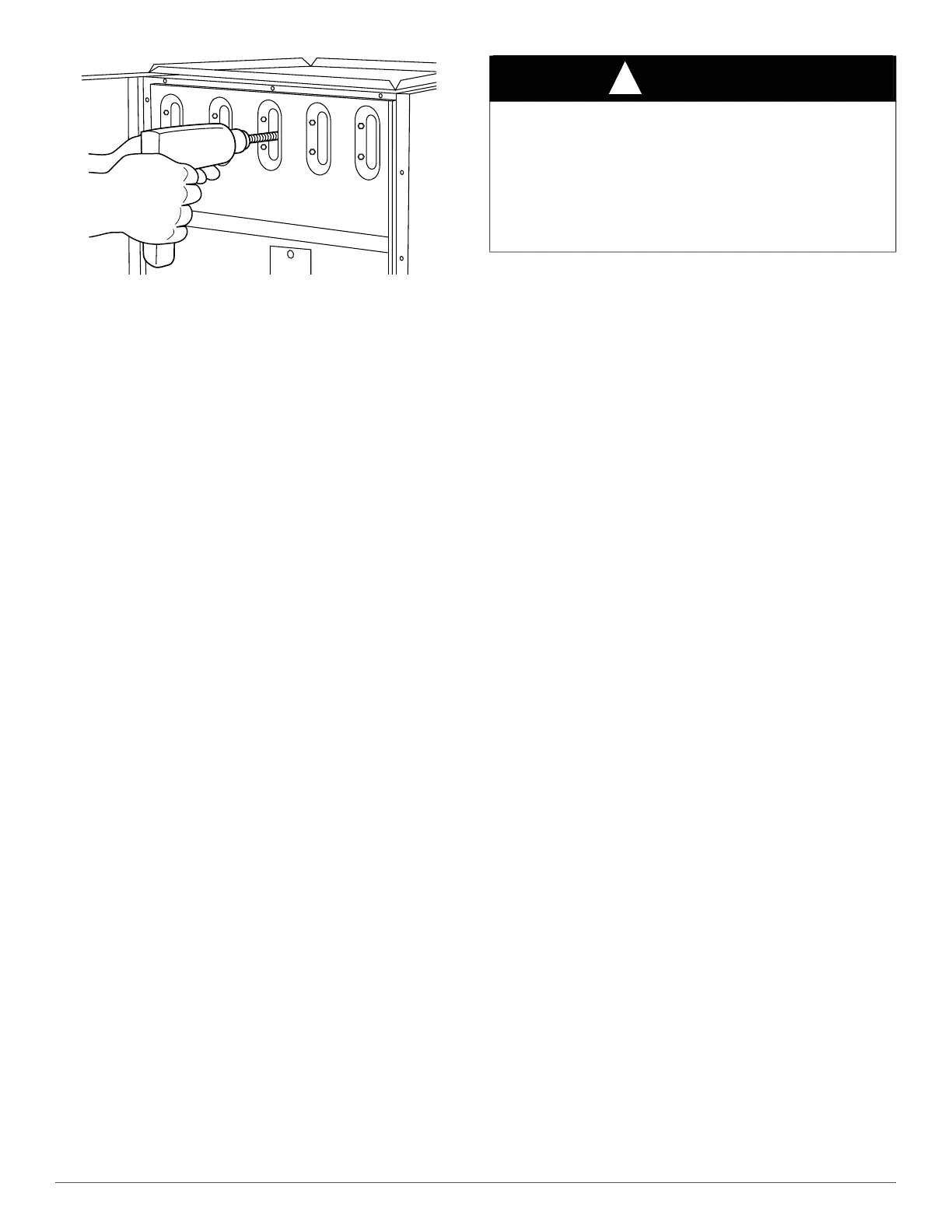
A91252
Fig. 51 – Cleaning Heat Exchanger Cell
(3.) Work cable in and out of cell 3 or 4 times to obtain
sufficient cleaning. DO NOT pull cable with great force.
Reverse drill and gradually work cable out.
(4.) Insert brush end of cable in burner inlet opening of cell, and
proceed to clean 2 lower passes of cell in same manner as
upper pass.
(5.) Repeat foregoing procedures until each cell in furnace has
been cleaned.
(6.) Using vacuum cleaner, remove residue from each cell.
(7.) Using vacuum cleaner with soft brush attachment, clean
burner assembly.
(8.) Clean flame sensor with fine steel wool.
(9.) Reinstall burner assembly. Center burners in cell openings.
10. Remove old sealant from cell panel and collector box flange.
11. Spray releasing agent on the heat exchanger cell panel where
collector box assembly contacts cell panel.
NOTE: A releasing agent such as cooking spray or equivalent (must not
contain corn or canola oil, aromatic or halogenated hydrocarbons or
inadequate seal may occur) and RTV sealant (G.E. 162, 6702, or
Dow-Corning 738) are needed before starting installation. DO NOT
substitute any other type of RTV sealant. G.E. 162 (P771-9003) is
available through RCD in 3-oz tubes.
12. Apply new sealant to flange of collector box and attach to cell panel
using existing screws, making sure all screws are secure.
13. Reconnect wires to the following components (Use connection
diagram on wiring label, if wires were not marked for reconnection
locations.):
a. Draft safeguard switch.
b. Inducer motor.
c. Pressure switches.
d. Limit over temperature switch.
e. Gas valve.
f. Hot surface igniter.
g. Flame-sensing electrode.
h. Flame rollout switches.
14. Reinstall internal vent pipe, if applicable.
15. Reinstall vent connector on furnace vent elbow. Securely fasten
vent connector to vent elbow with 2 field-supplied,
corrosion-resistant, sheet metal screws located 180_ apart.
16. Replace blower access door only if it was removed.
17. Set thermostat above room temperature and check furnace for
proper operation.
18. Verify blower airflow and speed changes between heating and
cooling.
19. Check for gas leaks.
SEQUENCE OF OPERATION
NOTE: Furnace control must be grounded for proper operation or else
control will lock out. Control is grounded through green/yellow wire
routed to gas valve and burner box screw. Using the schematic diagram
in Fig. 47, follow the sequence of operation through the different modes.
Read and follow the wiring diagram very carefully.
NOTE: If a power interruption occurs during a call for heat (W/W1 or
W/W1-and-W2), the control will start a 90-second blower-only ON
period two seconds after power is restored, if the thermostat is still
calling for gas heating. The LED light will flash code 12 and display will
show (12.1) during the 90-sec period, after which the LED will be ON
continuous, as long as no faults are detected. After the 90-second period,
the furnace will respond to the thermostat normally.
The blower door must be installed for power to be conducted through the
blower door interlock switch ILK to the furnace control CPU,
transformer TRAN, inducer motor IDM, blower motor BLWM,
hot-surface igniter HSI, and gas valve GV.
1. Comfort Heat
®
Technology - Two-Stage Heating (Adaptive
Mode) with Single-Stage Thermostat
See Fig. 30 for thermostat connections
NOTE: Heating Thermostat Type (Htt) can be set to either single stage
(1St) or two-stage (2St) on the control (see the Furnace Control
Programming and Navigation section of this instruction). When set to
(1St), the adaptive heating mode will be used in response to a call for
heat. When the W2 thermostat terminal is energized it will always cause
high-heat operation when the R-to-W circuit is closed, regardless of the
setting of (Htt). This furnace can operate as a two-stage furnace with a
single-stage thermostat because the furnace control CPU includes a
programmed adaptive sequence of controlled operation, which selects
low-heat or high-heat operation. This selection is based upon the stored
history of the length of previous gas-heating periods of the single-stage
thermostat.
The furnace will start up in either low- or high-heat. If the furnace starts
up in low-heat, the control CPU determines the low-heat on-time (from 0
to 16 minutes) which is permitted before switching to high-heat.
If the power is interrupted, the stored history is erased and the control
CPU will select low-heat for up to 16 minutes and then switch to
high-heat, as long as the thermostat continues to call for heat.
Subsequent selection is based on stored history of the thermostat cycle
times.
The wall thermostat “calls for heat”, closing the R-to-W circuit. The
furnace control performs a self-check, verifies the low-heat and
high-heat pressure switch contacts LPS and HPS are open, and starts the
inducer motor IDM in high-speed.
a. Inducer Prepurge Period
(1.) If the furnace control CPU selects low-heat operation the
inducer motor IDM comes up to speed, the low-heat
pressure switch LPS closes, 24 VAC power is supplied for a
field installed humidifier at the HUM terminal and the
furnace control CPU begins a 15-second prepurge period. If
the low-heat pressure switch LPS fails to remain closed the
inducer motor IDM will remain running at high-speed.
After the low-heat pressure switch re-closes the furnace
WARNING
!
FIRE OR EXPLOSION HAZARD
Failure to follow this warning could result in personal injury, death,
and/or property damage.
Never purge a gas line into a combustion chamber. Never test for gas
leaks with an open flame. Use a commercially available soap solution
made specifically for the detection of leaks to check all connections. A
fire or explosion may result causing property damage, personal injury
or loss of life.