58TP0B/58TP1B: Installation, Start-up, Operating and Service and Maintenance Instructions
Manufacturer reserves the right to change, at any time, specifications and designs without notice and without obligations.
23
Sidewall Venting
This furnace is not approved for direct sidewall horizontal venting.
Per section 12.4.3 of the NFPA 54/ANSI Z223.1, any listed mechanical
venter may be used, when approved by the authority having jurisdiction.
Select the listed mechanical venter to match the BTUh input of the
furnace being vented. Follow all manufacturer’s installation
requirements for venting and termination included with the listed
mechanical venter.
Caution!! For the following applications, use the minimum vertical heights as specified below.
For all other applications, follow exclusively the National Fuel Gas Code.
NOTE: All vent configurations must also meet National Fuel Gas Code venting requirements NFPA 54/ANSI Z223.
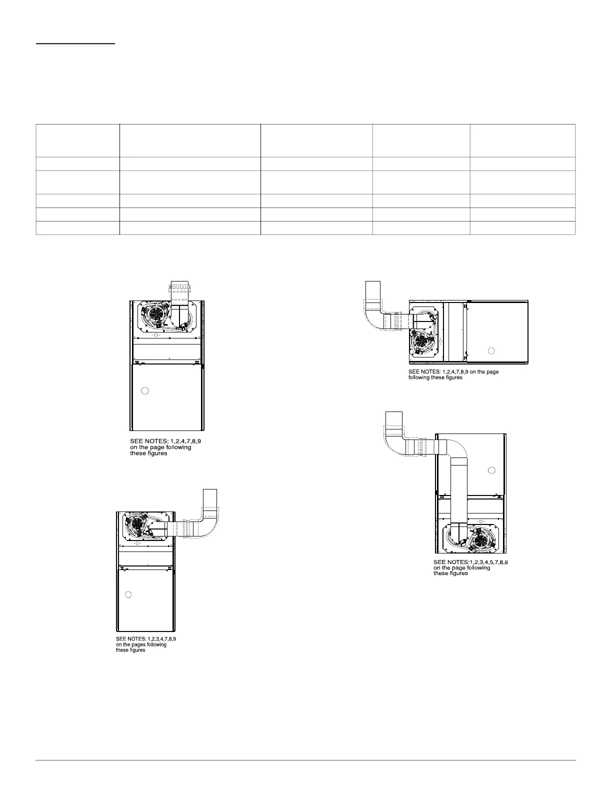
A03208
Fig. 32 – Upflow Application - Vent Elbow Up
A03209
Fig. 33 – Upflow Application - Vent Elbow Right
A03213
Fig. 34 – Horizontal Left Application - Vent Elbow Left
A03210
Fig. 35 – Downflow Application - Vent Elbow Up then Left
Table 9 – Recommended Minimum Vent Height Per Furnace and Vent Orientation
FURNACE
ORIENTATION
VENT ORIENTATION
FURNACE INPUT
(BTUH/HR)
MIN. VENT
DIAMETER
IN. (mm)
*
*. 4-in. (102 mm) inside casing or vent guard
MIN. VERTICAL VENT
HEIGHT
FT. (M)
†
†. Including 4 in. (102 mm) vent section(s)
Downflow Vent elbow up then left - Fig. 35 110,000 5 (127) 10 (3.0)
Downflow Vent elbow left, then up - Fig. 38
110,000
132,000
5 (127) 12 (3.6)
Downflow Vent elbow up, then right - Fig. 39 110,000 5 (127) 10 (3.0)
Horizontal Left Vent elbow right, then up - Fig. 40 132,000 5 (127) 7 (2.1)
Horizontal Left Vent Elbow up - Fig. 41 132,000 5 (127) 7 (2.1)