58TP0B/58TP1B: Installation, Start-up, Operating and Service and Maintenance Instructions
Manufacturer reserves the right to change, at any time, specifications and designs without notice and without obligations.
15
An accessible manual equipment shutoff valve MUST be installed
external to furnace casing and within 6 ft. (1.8 M) of furnace. A 1/8-in.
(3 mm) NPT plugged tapping, accessible for test gauge connection,
MUST be installed immediately upstream of gas supply connection to
furnace and downstream of manual equipment shutoff valve.
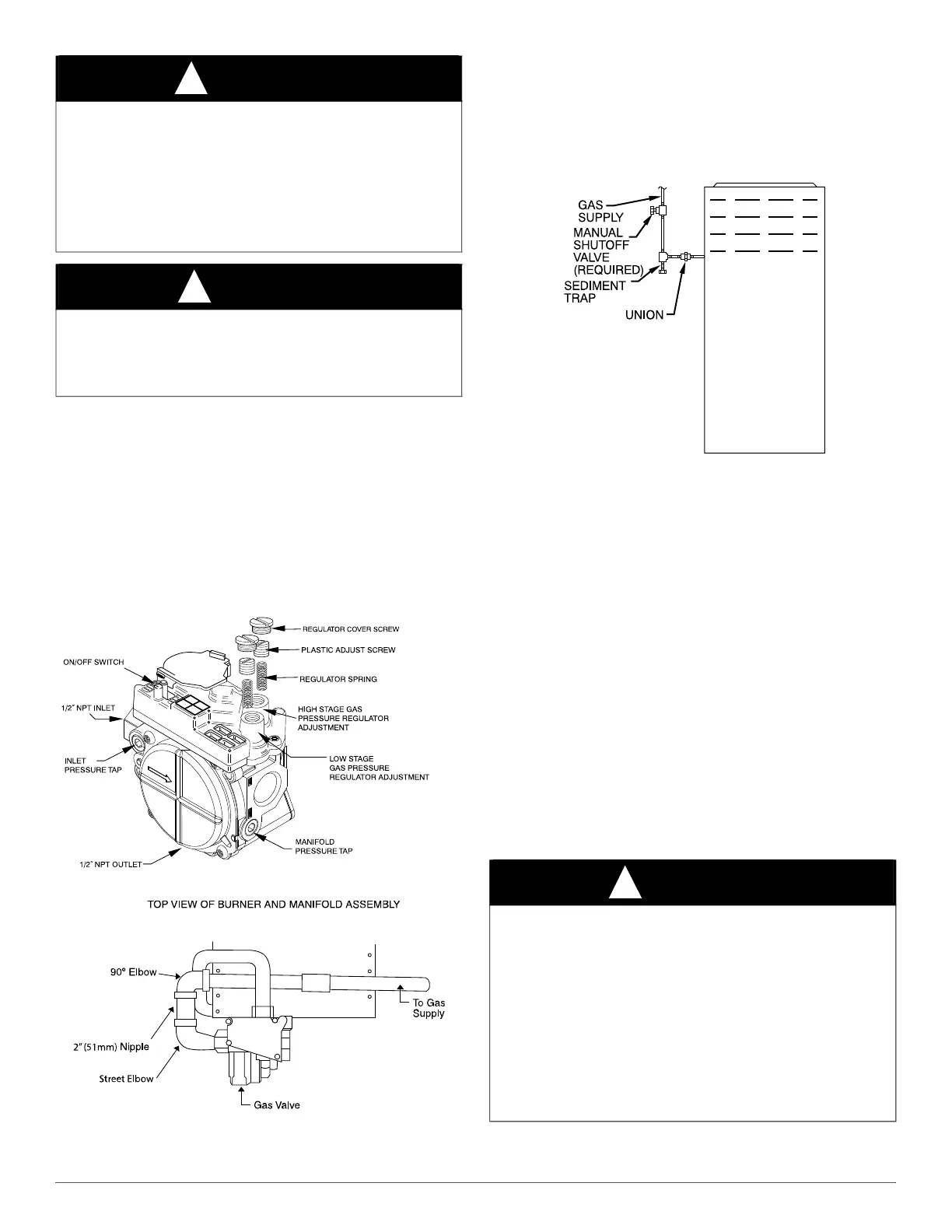
NOTE: The furnace gas control valve inlet pressure tap connection is
suitable to use as test gauge connection providing test pressure DOES
NOT exceed maximum 0.5 psig (14-in. w.c.) stated on gas control valve.
(See Fig. 21).
Some installations require gas entry on right side of furnace (as viewed
in upflow). (See Fig. 22).
A04167
Fig. 21 – Redundant Automatic Gas Control Valve
A08551
Fig. 22 – Burner and Manifold
Install a sediment trap in riser leading to furnace. (See Fig. 23). Connect
a capped nipple into lower end of tee. Capped nipple should extend
below level of furnace gas controls. Place a ground joint union between
furnace gas control valve and exterior manual equipment gas shutoff
valve.
A 1/8-in. (3 mm) NPT plugged tapping, accessible for test gauge
connection, MUST be installed immediately upstream of gas supply
connection to furnace and downstream of manual equipment shutoff
valve.
A02035
Fig. 23 – Typical Gas Pipe Arrangement
Piping should be pressure and leak tested in accordance with the current
addition of the NFPA 54/ANSI Z223 in the United States, local, and
national plumbing and gas codes before the furnace has been connected.
After all connections have been made, purge lines and check for leakage
at furnace prior to operating furnace.
If pressure exceeds 0.5 psig (14-in. w.c.), gas supply pipe must be
disconnected from furnace and capped before and during supply pipe
pressure test. If test pressure is equal to or less than 0.5 psig (14-in. w.c.),
turn off electric shutoff switch located on furnace gas control valve and
accessible manual equipment shutoff valve before and during supply
pipe pressure test. After all connections have been made, purge lines and
check for leakage at furnace prior to operating furnace.
The gas supply pressure shall be within the maximum and minimum
inlet supply pressures marked on the rating plate with the furnace
burners ON and OFF.
ELECTRICAL CONNECTIONS
See Fig. 24 for field wiring diagram showing typical field 115-V wiring.
Check all factory and field electrical connections for tightness.
Field-supplied wiring shall conform with the limitations of 63°F (33°C)
rise.
WARNING
!
FIRE OR EXPLOSION HAZARD
A failure to follow this warning could result in personal injury, death,
and/or property damage.
If local codes allow the use of a flexible gas appliance connector,
always use a new listed connector. Do not use a connector which has
previously served another gas appliance. Black iron pipe shall be
installed at the furnace gas control valve and extend a minimum of 2-in.
(51 mm) outside the furnace.
CAUTION
!
FURNACE DAMAGE HAZARD
Failure to follow this caution may result in furnace damage.
Connect gas pipe to furnace using a backup wrench to avoid damaging
gas controls and burner misalignment.
WARNING
!
ELECTRICAL SHOCK, FIRE OR EXPLOSION HAZARD
Failure to follow safety warnings could result in dangerous operation,
serious injury, death or property damage.
Improper servicing could result in dangerous operation, serious injury,
death or property damage.
- Before servicing, disconnect all electrical power to furnace.
- When servicing controls, label all wires prior to disconnection.
Reconnect wires correctly.
- Verify proper operation after servicing.
- Always reinstall access doors after completing service and
maintenance.