58TP0B/58TP1B: Installation, Start-up, Operating and Service and Maintenance Instructions
Manufacturer reserves the right to change, at any time, specifications and designs without notice and without obligations.
14
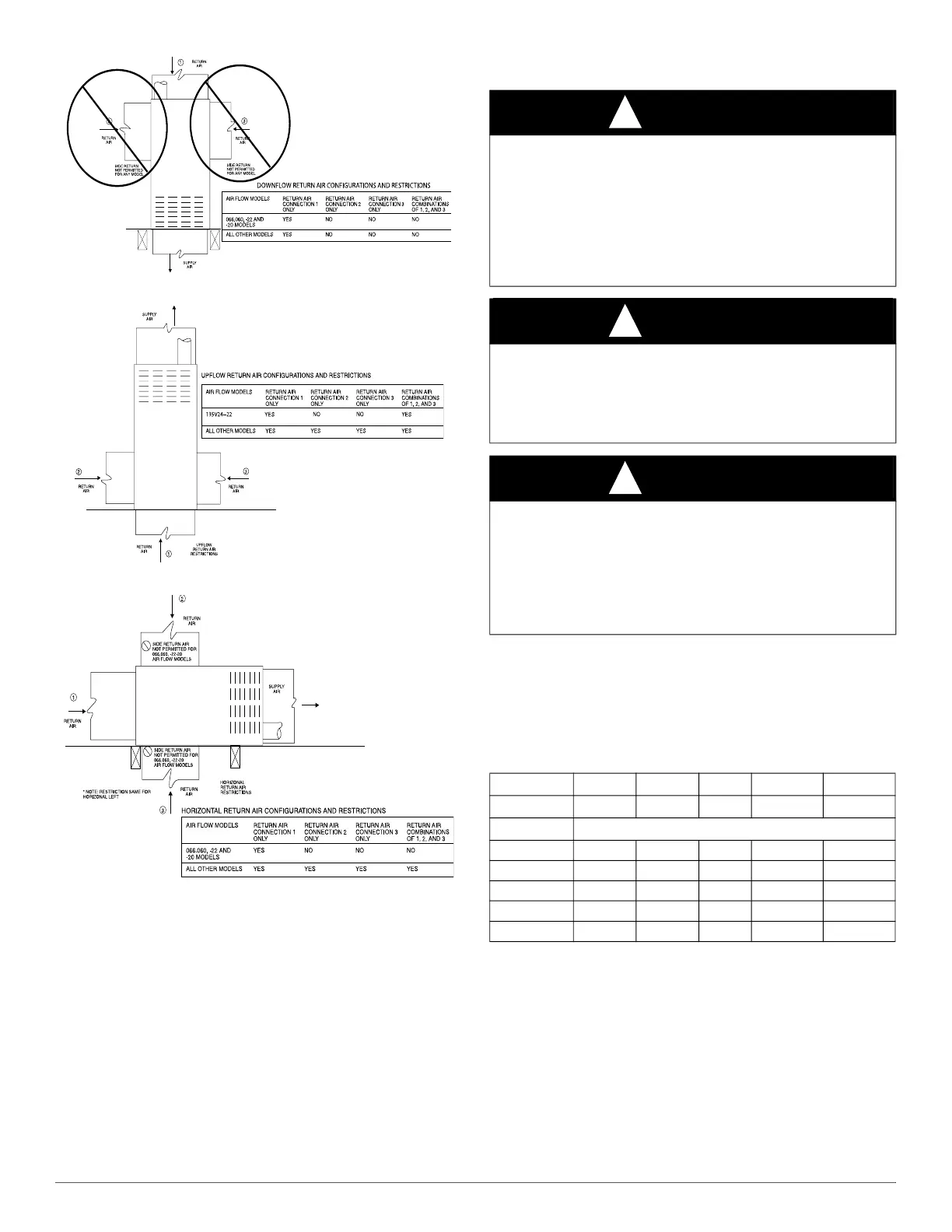
A02163
Fig. 18 – Downflow Return Air Configurations and Restrictions
A190054
Fig. 19 – Upflow Return Air Configurations and Restrictions
A02162
Fig. 20 – Horizontal Return Air Configurations and Restrictions
GAS PIPING
Gas piping must be installed in accordance with national and local
codes. Refer to current edition of NFPA 54/ANSI Z223 in the U.S.
Installations must be made in accordance with all authorities having
jurisdiction. If possible, the gas supply line should be a separate line
running directly from meter to furnace.
NOTE: In the state of Massachusetts:
1. Gas supply connections MUST be performed by a licensed
plumber or gas fitter.
2. When flexible connectors are used, the maximum length shall not
exceed 36 in. (915 mm).
3. When lever handle type manual equipment shutoff valves are used,
they shall be T-handle valves.
4. The use of copper tubing for gas piping is NOT approved by the
state of Massachusetts.
Refer to Table 5 for recommended gas pipe sizing. Risers must be used
to connect to furnace and to meter. Support all gas piping with
appropriate straps, hangers, etc. Use a minimum of 1 hanger every 6 ft.
(1.8 M). Joint compound (pipe dope) should be applied sparingly and
only to male threads of joints. Pipe dope must be resistant to the action
of propane gas.
NOTE: Cubic ft. of natural gas per hr for gas pressures of 0.5 psig
(14-in. w.c.) or less and a pressure drop of 0.5-in. w.c. (based on a 0.60
specific gravity gas). Ref: Chapter 6 current edition of NFPA 54/ANSI
Z223.
WARNING
!
FIRE OR EXPLOSION HAZARD
Failure to follow this warning could result in personal injury, death,
and/or property damage.
Never purge a gas line into a combustion chamber. Never test for gas
leaks with an open flame. Use a commercially available soap solution
made specifically for the detection of leaks to check all connections. A
fire or explosion may result causing property damage, personal injury
or loss of life.
WARNING
!
FIRE OR EXPLOSION HAZARD
Failure to follow this warning could result in personal injuriousness,
and/or property damage.
Use proper length of pipe to avoid stress on gas control assembly and a
gas leak.
WARNING
!
FIRE OR EXPLOSION HAZARD
Failure to follow this warning could result in personal injury, death,
and/or property damage.
Gas valve inlet and/or inlet pipe must remain capped until gas supply
line is permanently installed to protect the valve from moisture and
debris. Also, install a sediment trap in the gas supply piping at the inlet
to the gas valve.
Table 5 – Maximum Capacity of Pipe
Nominal: 1/2 (12.7) 3/4 (19.0) 1 (25.4) 1-1/4 (31.8) 1-1/2 (38.1)
Actual ID: 0.622 0.824 1.049 1.380 1.610
Length (ft) Capacity in Cubic Feet of Gravity
10 (3.0)
172 360 678 1390 2090
20 (6.0)
118 247 466 957 1430
30 (9.1)
95 199 374 768 1150
40 (12.1)
81 170 320 657 985
50 (15.2)
72 151 284 583 873