58TP0A/58TP1A: Installation, Start-up, Operating and Service and Maintenance Instructions
Manufacturer reserves the right to change, at any time, specifications and designs without notice and without obligations.
15
A02035
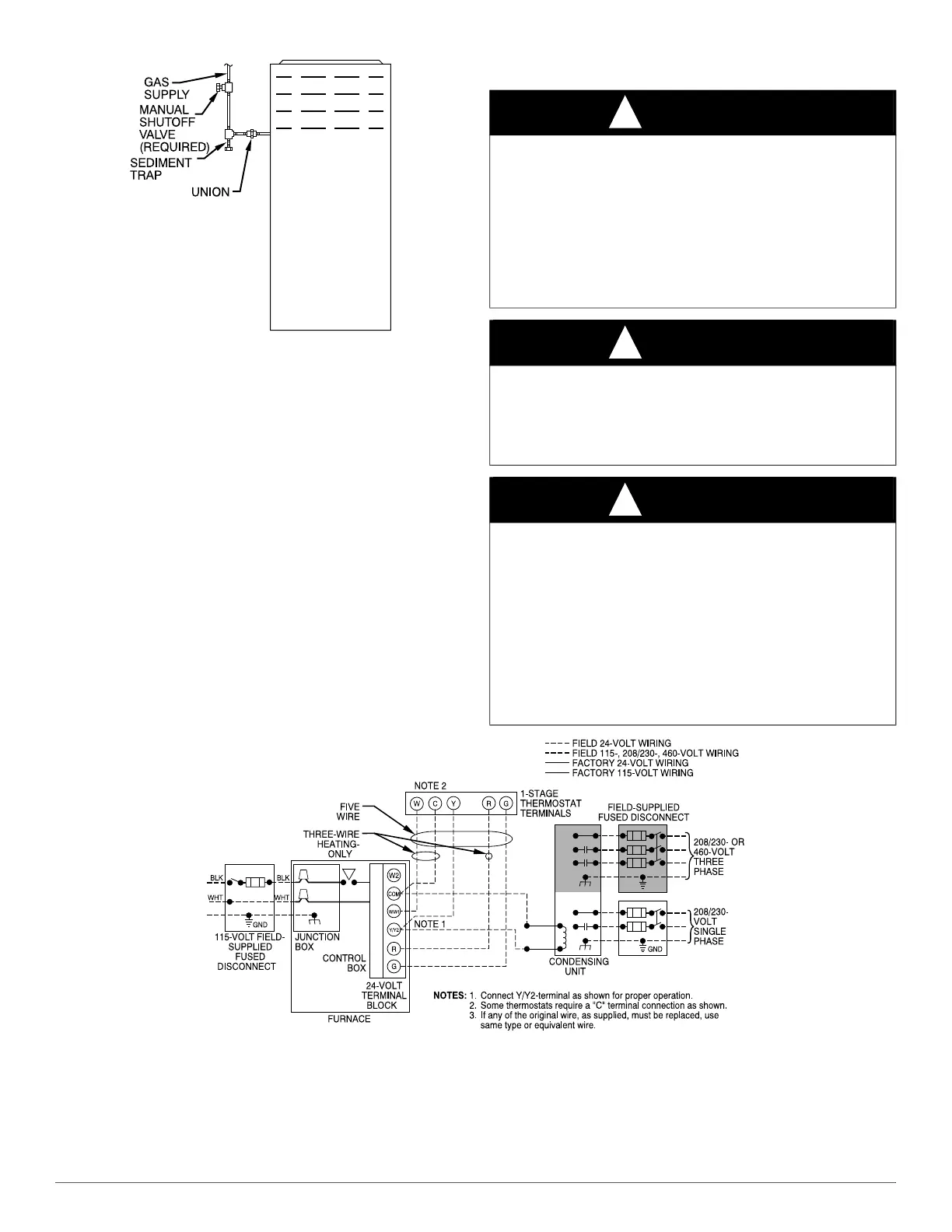
Fig. 23 – Typical Gas Pipe Arrangement
Piping should be pressure and leak tested in accordance with the current
addition of the NFGC in the United States, local, and national plumbing
and gas codes before the furnace has been connected. After all
connections have been made, purge lines and check for leakage at
furnace prior to operating furnace.
If pressure exceeds 0.5 psig (14-In. W.C.), gas supply pipe must be
disconnected from furnace and capped before and during supply pipe
pressure test. If test pressure is equal to or less than 0.5 psig (14-In.
W.C.), turn off electric shutoff switch located on furnace gas control
valve and accessible manual equipment shutoff valve before and during
supply pipe pressure test. After all connections have been made, purge
lines and check for leakage at furnace prior to operating furnace.
The gas supply pressure shall be within the maximum and minimum
inlet supply pressures marked on the rating plate with the furnace
burners ON and OFF.
ELECTRICAL CONNECTIONS
See Fig. 24 for field wiring diagram showing typical field 115-v wiring.
Check all factory and field electrical connections for tightness.
Field-supplied wiring shall conform with the limitations of 63°F (33°C)
rise.
A95236
Fig. 24 – Field Wiring Diagram
WARNING
!
ELECTRICAL SHOCK, FIRE OR EXPLOSION HAZARD
Failure to follow safety warnings could result in dangerous operation,
serious injury, death or property damage.
Improper servicing could result in dangerous operation, serious injury,
death or property damage.
- Before servicing, disconnect all electrical power to furnace.
- When servicing controls, label all wires prior to disconnection.
Reconnect wires correctly.
- Verify proper operation after servicing.
WARNING
!
ELECTRICAL SHOCK HAZARD
Failure to follow this warning could result in personal injury or death.
Blower access panel door switch opens 115-v power to control. No
component operation can occur. Do not bypass or close switch with
panel removed.
WARNING
!
ELECTRICAL SHOCK AND FIRE HAZARD
Failure to follow this warning could result in personal injury, death, or
property damage.
The cabinet MUST have an uninterrupted or unbroken ground
according to NEC NFPA 70 or local codes to minimize personal injury
if an electrical fault should occur. This may consist of electrical wire,
conduit approved for electrical ground or a listed, grounded power cord
(where permitted by local code) when installed in accordance with
existing electrical codes. Refer to the power cord manufacturer’s
ratings for proper wire gauge. Do not use gas piping as an electrical
ground.