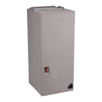
Fig. 3 — Unit Dimensions — 42BHE Fan Coil Base Unit (No Controls)
NOTES:
1. Unit measurements on drawings and in tables are shown in inches and (millimeters).
2. Right hand shown, left hand opposite.
3. All dimensions are in inches ±1/4 in.(6 mm).
4. Product specifications are subject to change without notice.
5. Right hand shown, left hand opposite.
6. Allow adequate spacing for maneuverability around unit to allow service through recommended access area.
7. “C” dimension is measured from coil side of unit.
8. Mixing Box option will vary return duct dimensions, refer to mixing box details, Fig. 19 page 18.
UNIT
42BHE
DIMENSIONS — in. (mm)
M
Fan
Size
Depth Width Height
Supply Duct Return Duct Mounting Holes
ABCDEFGJK
06 9 x 4
36
(914)
28
(711)
19-3/4
(502)
7-1/8
(181)
10-1/2
(267)
14-1/2
(368)
2-1/4
(57)
24-1/4
(616)
14
(356)
2-3/4
(70)
27-1/4
(686)
35-1/4
(895)
2
(51)
08 9 x 6
36
(914)
28
(711)
19-3/4
(502)
8-1/2
(216)
10-1/2
(267)
14
(356)
2-1/4
(57)
24-1/4
(616)
14
(356)
2-3/4
(70)
27-1/4
(686)
35-1/4
(895)
2
(51)
10 10 x 4
37-1/2
(953)
37
(940)
21-1/2
(546)
7-1/8
(181)
11-5/8
(295)
15-1/4
(387)
2-1/4
(57)
33-1/4
(845)
15-3/4
(401)
2-7/8
(73)
36-1/4
(921)
37
(940)
2
(51)
12 10 x 7
37-1/2
(953)
37
(940)
21-1/2
(546)
10
(254)
11-5/8
(295)
14
(356)
2-1/4
(57)
33-1/4
(845)
15-3/4
(401)
2-7/8
(73)
36-1/4
(921)
37
(940)
2
(51)
16 11 x 10
37-3/4
(959)
47
(1194)
21-1/2
(546)
13-3/8
(340)
12-3/4
(324)
16-3/4
(425)
2-1/4
(57)
43-7/8
(1115)
15-3/4
(401)
2-7/8
(73)
46-1/4
(1175)
37
(940)
1-1/2
(38)
20 12 x 9
40-1/4
(1022)
48
(1219)
24
(610)
12-1/2
(216)
13-3/4
(349)
17-3/4
(451)
2-1/4
(57)
44-1/4
(1124)
18
(457)
2-7/8
(73)
47-1/4
(1200)
39-1/2
(1033)
2
(51)
30 12 x 12
40-1/4
(1022)
48
(1219)
32-1/4
(819)
15-7/8
(403)
13-3/4
(349)
16
(406)
7-1/4
(184)
44-1/4
(1124)
26-1/2
(673)
1-1/4
(32)
47-1/4
(1200)
39-1/2
(1033)
2
(51)
40 15 x 12
43-1/2
(1105)
62
(1575)
32-1/4
(819)
16-3/8
(416)
16-1/8
(410)
22-3/4
(578)
6-1/4
(159)
58-1/4
(1480)
26-1/2
(673)
1-1/4
(32)
61-1/4
(1556)
42-1/2
(1080)
2
(51)

 Loading...


