2
INTRODUCTION
The following contains general installation instructions for the
42BHE, BVE fan coil units. See Fig. 2 for components. Refer to
the unit wiring diagram installed on the blower housing or specific
manufacturer literature for any other type of factory-mounted
controls.
See drawings for unit configurations, dimensions, clearances, and
pipe connections. Refer to unit wiring label for all electrical con-
nections. Follow NEC (National Electrical Code) and local codes.
INSTALLATION
Step 1 — Unpack and Inspect Unit
Remove shipping wraps from unit and check shipment against
shipping list. Check for concealed shipping damage. If ship-
ment is damaged or incomplete, file claim with transportation
company and contact your local Carrier representative
immediately.
Step 2 — Protect Unit from Damage
To maintain warranty, protect unit against adverse weather condi-
tions, theft or vandalism on the jobsite.
The described equipment IS NOT suitable for outdoor installa-
tions. The equipment should never be stored or installed where it
may be subjected to a hostile environment such as rain, snow, or
extreme temperatures.
Step 3 — Prepare Jobsite
To save time and to reduce the possibility of costly errors, set up a
complete sample installation in a typical room at jobsite. Check all
critical dimensions such as pipe, wire and duct connection require-
ments. Refer to job drawings and product dimension drawings as
required. Instruct all trades in the appropriate part of the installa-
tion. For unit component identification, refer to Fig. 2. For unit di-
mensions, refer to Fig. 3-5 for 42BHE units. Refer to Fig. 6-8 for
42BVE units.
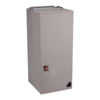
Fig. 2 — Component Identification (42BHE Units Shown)

 Loading...


