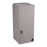
Fig. 6 — Unit Dimensions — 42BVE Fan Coil Base Unit (No Controls)
Dimensions may vary with options ordered.
NOTES:
1. Right hand shown, Left hand opposite.
2. All dimensions are +/- 1/4” (+/- 6 mm).
3. Drain pan removal is on the piping side of the unit.
4. Allow adequate spacing or maneuverability of unit to allow service through recommended access area.
5. Dimensions in parenthesis are in millimeters.
6. “C” dimension is measured from coil side of unit.
7. Product specifications are subject to change without notice.
8. Mixing Box option will vary return duct dimensions, refer to mixing box details, Fig. 19 page 18.
UNIT
42BVE
DIMENSIONS — in. (mm)
Fan Size Depth Width Height
Supply Duct Return Duct
AB CEF
06 9 x 4
20
(508)
28
(711)
36-1/2
(927)
7-1/8
(181)
10-1/2
(267)
16-3/4
(425)
24
(610)
16-1/2
(419)
08 9 x 6
20
(508)
28
(711)
36-1/2
(927)
8-1/2
(216)
10-1/2
(267)
15-1/4
(387)
24
(610)
16-1/2
(419)
10 10 x 4
22
(559)
37
(940)
39-3/8
(1000)
7-1/8
(181)
11-9/16
(294)
24-1/2
(622)
33
(838)
18-1/4
(464)
12 10 x 7
22
(559)
37
(940)
39-3/8
(1000)
9-15/16
(252)
11-9/16
(294)
21-1/2
(546)
33
(838)
18-1/4
(464)
16 11 x 10
22
(559)
47
(1194)
39-3/8
(1000)
13-3/8
(340)
12-3/4
(324)
16-3/4
(425)
43
(1092)
18-1/4
(464)
20 12 x 9
24
(610)
48
(1219)
45-1/8
(1146)
12-1/2
(318)
13-3/4
(349)
17-3/4
(451)
44
(1118)
20-3/4
(527)
30 12 x 12
28
(711)
48
(1219)
54-3/16
(1376)
15-7/8
(403)
13-3/4
(349)
16
(406)
44
(1118)
29
(737)
40 15 x 12
28
(711)
62
(1575)
57-5/8
(1464)
16-7/16
(418)
16-1/16
(408)
22-3/4
(578)
58
(1473)
29
(737)

 Loading...


