11
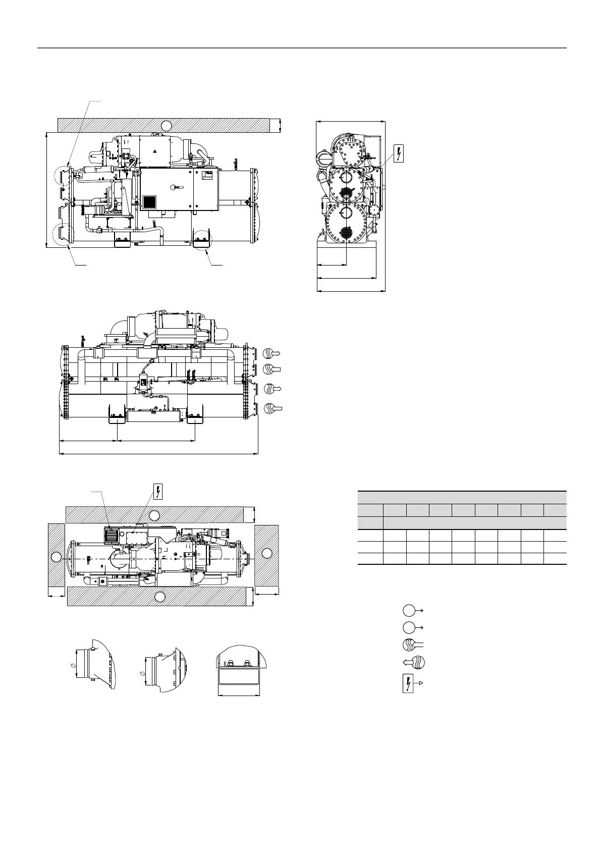
3 - DIMENSIONS, CLEARANCES
3.1 - 61XWHLZE/61XWH-ZE/61XWHHZE 03-05-07
1200B
D
Inlet air
connection
1
1
2
700
700
1000
H
2
Detail A Detail B Detail C
250
G
F
See detail B
1
600
E
A
450
900
C
See detail A See detail C
NOTES:
• Drawings are not contractually binding. Before designing an installation, consult the certied dimensional drawings
supplied with the unit or available on request.
• For the positioning of the xing points, weight distribution and centre of gravity coordinates please refer to the
dimensional drawings.
61XWHLZE/61XWH-ZE/61XWHHZE
A B C D E F G H
Model Dimensions in mm
3 1594 723 981 2724 982 141,3 141,3 2600
5 1745 891 1041 3059 1039 168,3 168,3 2900
7 1968 1007 1079 3290 1170 219,1 219,1 3100
Legend
All dimensions are given in mm
1
Services clearances required
2
Space required to remove cooler tubes
Inlet water
Outlet water
Electrical supply entry
 Loading...