26
Another solution consists of draining the hydronic circuits
exposed to temperatures below 0°C (must be used for units
with plate heat exchangers). If the unit is not used for an
extended period, protect it by circulating a protective
solution. Please consult a specialist.
A third solution is to order the ‘evaporator frost protection’
option (factory-installed - an electric heater on the evapo-
rator).
If the hydronic module option is used, the evaporator and
hydronic module frost protection option (additional electric
heaters on the hydronic module and the evaporator) must
also be ordered to ensure protection of the hydronic module
down to -20°C.
If option 41 has been ordered for the 30RB 162-262 “B”
standard units (only in this case) and if the accessory water
inlet/outlet extension pipe has been ordered, a heater must
be installed for each extension to ensure that the water
pipes are protected down to -20°C outside temperature.
The heat exchanger temperature sensors are part of its frost
protection: if piping trace heaters are used, ensure that the
external heaters do not affect the measurement of these
sensors.
NOTE: With 30RB 162-262 “B” units with option 280 and
30RB 302-802 units, the hydronic module can be protected
down to -10°C without the evaporator and hydronic module
frost protection option provided that:
• the evaporator frost protection option is ordered
• the pump starts up periodically to allow water
circulation in the hydronic circuit. If the system is
isolated by a valve, it is imperative to install a bypass
as indicated below.
> 0°C to 46°C - - - -
-10°C to 0°C Option 41
or
Appropriate frost protection
solution (e.g. glycol)
Option 42A*
or
Appropriate frost protection
solution (e.g. glycol)
Option 41
or
Appropriate frost protection solution
(e.g. glycol)
or
Drain the water circuits
Option 42A*
or
Appropriate frost protection solution
(e.g. glycol)
or
Drain the water circuits
or
Option 41 and hydronic kit pump
cycling*
-20°C to 0°C Option 42A*
or
Appropriate frost protection solution
(e.g. glycol)
or
Drain the water circuits
* Allow pump circulation. If a valve is included, install a bypass (see “Winter position” diagram).
Unit
Water system
Closed
Closed
Open
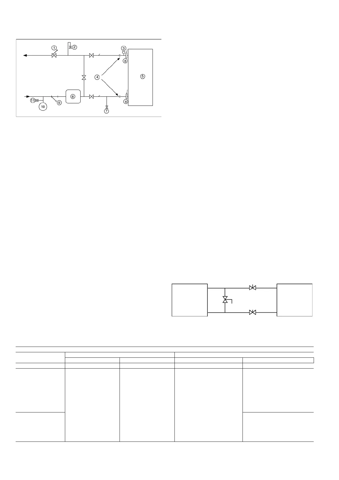
8.2.5 - Unit without hydronic module option
1 Control valve
2 Air vent
3 Flow switch for the evaporator (supplied)
4 Flexible connection
5 Heat exchanger
6 Temperature sensor (supplied)
7 Drain
8 Buer tank (if needed)
9 Filter (mesh size: 1.2 mm = 20 mesh)
10 Expansion tank
11 Fill valve
All units are equipped with a factory-set flow switch. The
unit must be interlocked with the chilled-water pump, if
the unit is not equipped with the hydronic option module.
Terminals 34 and 35 are provided for field installation of
the chilled water pump interlock (auxiliary contact for
pump operation to be wired on site).
The standard unit does not include any particular frost
protection when it has shut down. It is therefore essential
to check that there is no risk of the water in the hydronic
circuit freezing during winter temperature conditions. If
this may be the case it is essential to add an appropriate
anti-freeze solution to protect the hydronic circuit down to
the minimum temperature minus 10 K.
 Loading...