27
ATTENTION: If the recommendations above are not
followed, any resulting frost damage is not covered by the
guarantee.
The frost protection and electric heater solutions can be
combined. If protection by electric heater is used, do not
switch off the power supply to the unit.
IMPORTANT: The main unit disconnect switch, the
auxiliary heater protection switch as well as the control
circuit switch must always remain closed (to locate the
components, please refer to the wiring diagram).
IMPORTANT: Depending on the climatic conditions in
your area you must do the following when you shut the
unit down in winter:
• Add ethylene glycol with an adequate concentration
to protect the installation up to a temperature of 10 K
below the lowest temperature likely to occur at the
installation site.
• If the unit is not used for an extended period, it is
recommended to drain it, and as a safety precaution
add ethylene glycol to the heat exchanger, using the
water entering purge valve connection.
• At the start of the next season, refill the unit with water
and add an inhibitor.
• For the installation of auxiliary equipment, the instal-
ler must comply with basic regulations, especially for
minimum and maximum flow rates, which must be
between the values listed in the operating limit table
(application data).
• If any heat transfer circuit is emptied for longer than
a month, the complete circuit must be placed under
nitrogen charge to avoid any risk of corrosion by
differential aeration. If the heat transfer fluid does
not comply with Carrier recommendations, nitrogen
must be charged immediately.
For this type of operation the ‘Twinning’ option must be
ordered.
The units supplied are then equipped with an additional
sensor connected to the electronic board and located in
the control box.
This sensor must be used when master/slave assembly
control at the water outlet is used (it is not required for
entering water control).
The customer must connect the two units via a communi-
cation bus (0.75 mm
2
, twisted and shielded). Consult the
30RB Pro-Dialog Plus control manual for the connection
addresses.
Master/slave operation is only possible, when the units are
installed in parallel. It is not possible, if the units are
installed in series.
All parameters, required for the master/slave function must
be configured using the Service Configuration menu. All
remote controls of the master/slave assembly (start/stop, set
point, load shedding etc.) are controlled by the unit configured
as master and must only be applied to the master unit.
Each unit controls its own water pump. If there is only one
common pump, in cases with variable flow, isolation valves
must be installed on each unit. They will be activated at the
opening and closing by the control of each unit (in this case
the valves are controlled using the dedicated water pump
outputs). See the 30RB Pro-Dialog Plus Control IOM for
a more detailed explanation.
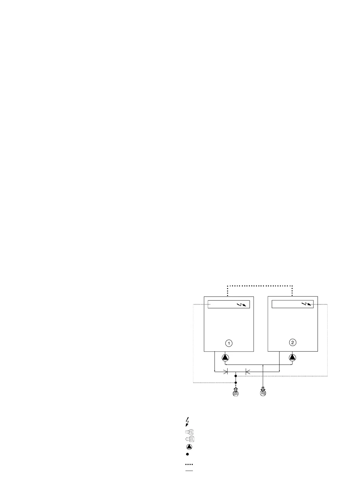
1 Master unit
2 Slave unit
Control boxes of the master and slave units
Water inlet
Water outlet
Water pumps for each unit (included as standard for units with hydronic
module)
Additional sensors for leaving water control, to be connected to channel 1
of the slave boards of each master and slave unit
CCN communication bus
Connection of two additional sensors
 Loading...