12
NOTE: Non-contractual drawings.
When designing an installation, refer to the certified
dimensional drawings, available on request.
For the positioning of the fixing points, weight distribution
points and centre of gravity coordinates please refer to the
dimensional drawings.
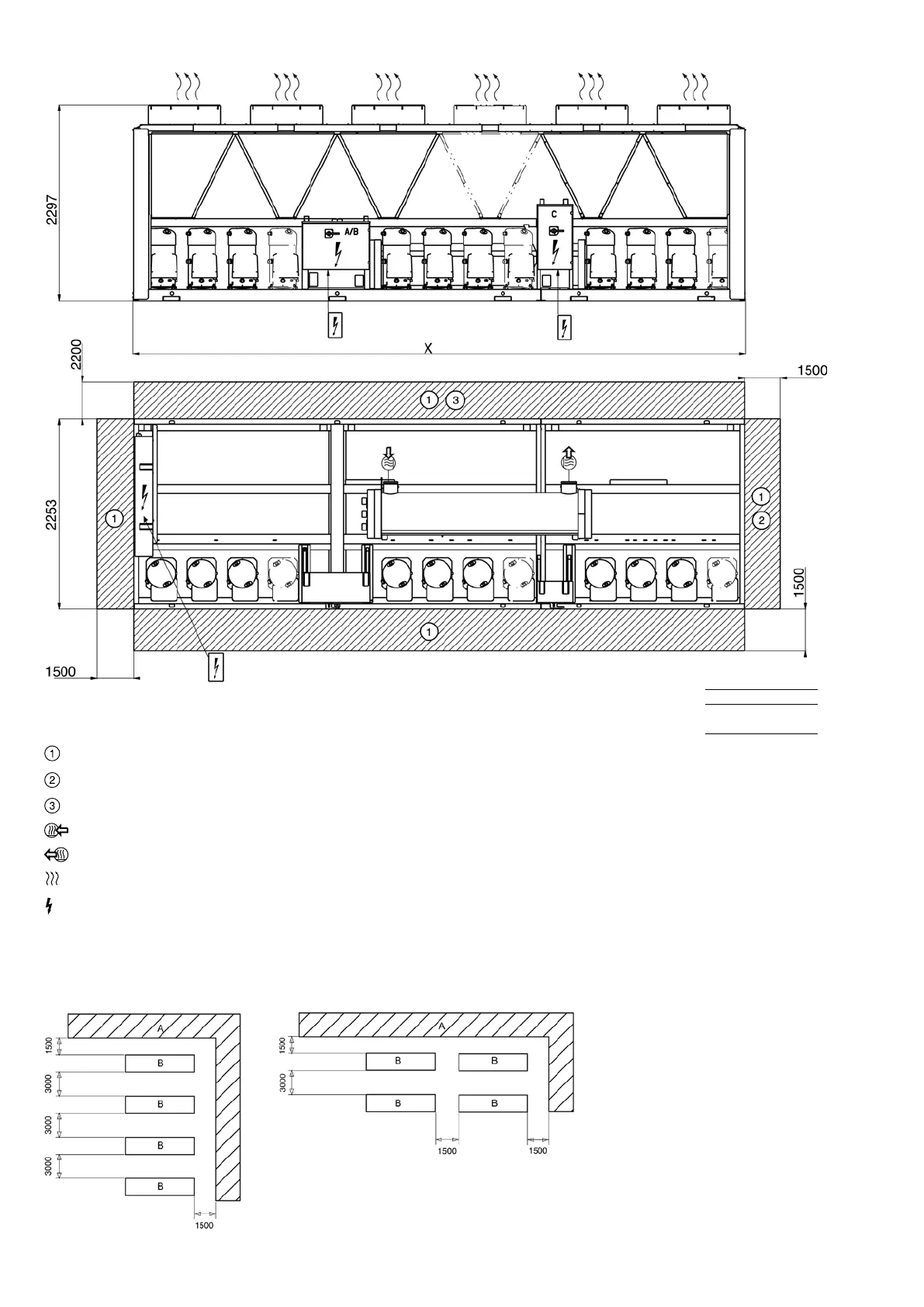
Power connection
circuit C
For user control connection
5992
7186
Power connection
circuits A and B
NOTE: If the walls are higher than 2 m, contact the factory
In case of multiple chillers (up to four units), the respective clearance between them
should be increased from 1500 to 3000 mm for the side space requirement.
If necessary, add the required clearances for evaporator tube or coil removal.
A Wall
B Units
Clearances required for maintenance and air ow
Clearances recommended for evaporator tube removal
Clearances recommended for heat exchanger removal
Water inlet
Water outlet
Air outlet, do not obstruct
Control box
 Loading...