28 Specifications subject to change without notice. CAS-072-153-01SI Rev. A
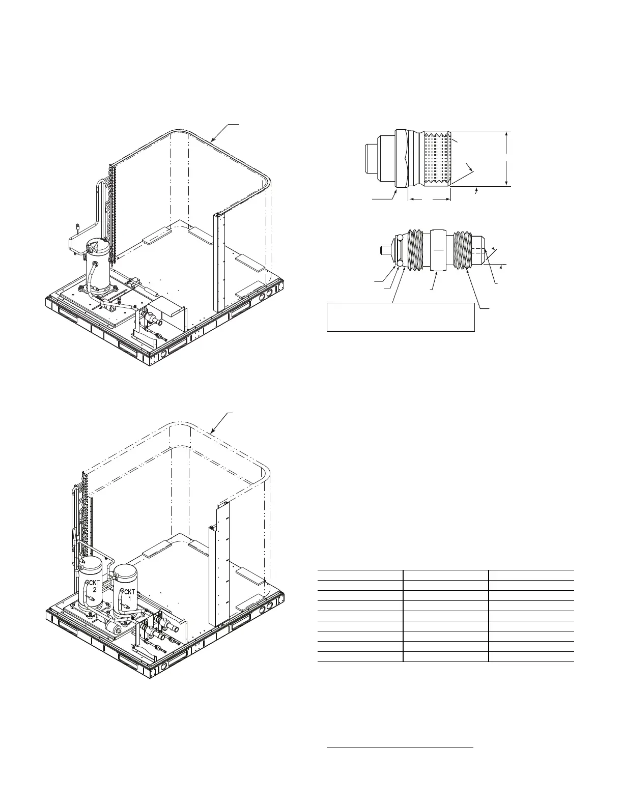
FACTORY HIGH-FLOW ACCESS PORTS
There are two additional access ports in the system - on the
suction tube between the compressor and the suction ser-
vice valve and on the liquid tube near the liquid service
valve (see Fig. 28 and 29). These are brass fittings with
black plastic caps. The hose connection fittings are stan-
dard 1/4-in. SAE Male Flare couplings.
Fig. 28 — Typical Interior, Single-Circuit Unit
(CAS091 shown)
Fig. 29 — Typical Interior, Two-Circuit Unit
(CAS153 shown)
The brass fittings are two-piece High Flow valves, with a
receptacle base brazed to the tubing and an integral
spring-closed check valve core screwed into the base.
See Fig. 30. This check valve is permanently assembled
into this core body and cannot be serviced separately;
replace the entire core body if necessary. Service tools are
available from Fast Parts that allow the replacement of the
check valve core without having to recover the entire sys-
tem refrigerant charge. Apply compressor refrigerant oil to
the check valve core’s bottom o-ring. Install the fitting body
with 96 ±10 in-lbs (1085 ±23 N-cm) of torque; do not
over-tighten.
Fig. 30 — CoreMax
1
Access Port Assembly
Comfort Alert Diagnostic Module
The Comfort Alert Diagnostic Module (CADM) monitors and
analyzes data from the Copeland Scroll three-phase com-
pressor and the thermostat demand. The CADM also pro-
vides a 3-minute anti-recycle time delay to compressor cy-
cling. Each compressor has a separate CADM module.
The CADM detects causes for electrical and system related
failures without any sensors. Flashing LEDs communicate
the Alert codes to guide service technicians in accurately
and quickly troubleshooting the system and determining
root cause for the failure.
Inputs to the CADM include 24-vac power, thermostat Y1
or Y2, compressor contactor coil (common side) and com-
pressor power leads (from the compressor contactor). See
Table 21.
Control of the compressor contactor coil is through a nor-
mally closed (power on the module) contact between termi-
nals P and C.
Communications of status and alert conditions is through
three LEDs located on the top edge of the module housing
(see Fig. 31): POWER (green), ALERT (yellow), and TRIP
(red).
1. CoreMax is a registered trademark of Fastest, Inc.
Table 21 — Comfort Alert Diagnostic Module Inputs
INPUT TERMINAL VOLTAGE
Control Power R 24-v
Demand
a
a All models require at least one 2-stage CADM.
Y2 24-v
Control Common C 24-v
Cooling Y 24-v
Contractor Coil P 24-v
Line A T1 Line
Line B T2 Line
Line C T3 Line
1/2-20 UNF RH
30°
0.596
.47
5/8" Hex
Seat
Core
Washer
Depressor per AHRI 720
+.01/-.035
From Face of Body
7/16-20 UNF RH
O-Ring
45°
1/2" Hex
This surface provides a metal to metal seal when
torqued into the seat. Appropriate handling is
required to not scratch or dent the surface.
(Part No. EC39EZ067)



 To Next Page