CAS-072-153-01SI Rev. A Specifications subject to change without notice. 9
Suction Riser
A suction riser condition exists when the outdoor unit is lo-
cated above the indoor (evaporator) unit and suction vapor
must flow vertically up to return to the compressor. Oil return
is a concern when the suction tube size is too large to pro-
duce the minimum refrigerant velocity to ensure oil return at
minimum load conditions.
Check Table 10 for maximum suction tube size for
CAS units at minimum load conditions. Consider suction
speed riser (reduced tube size for vertical segment only) or
double suction riser arrangement if the planned suction tube
size does not provide necessary minimum flow-rates for this
riser.
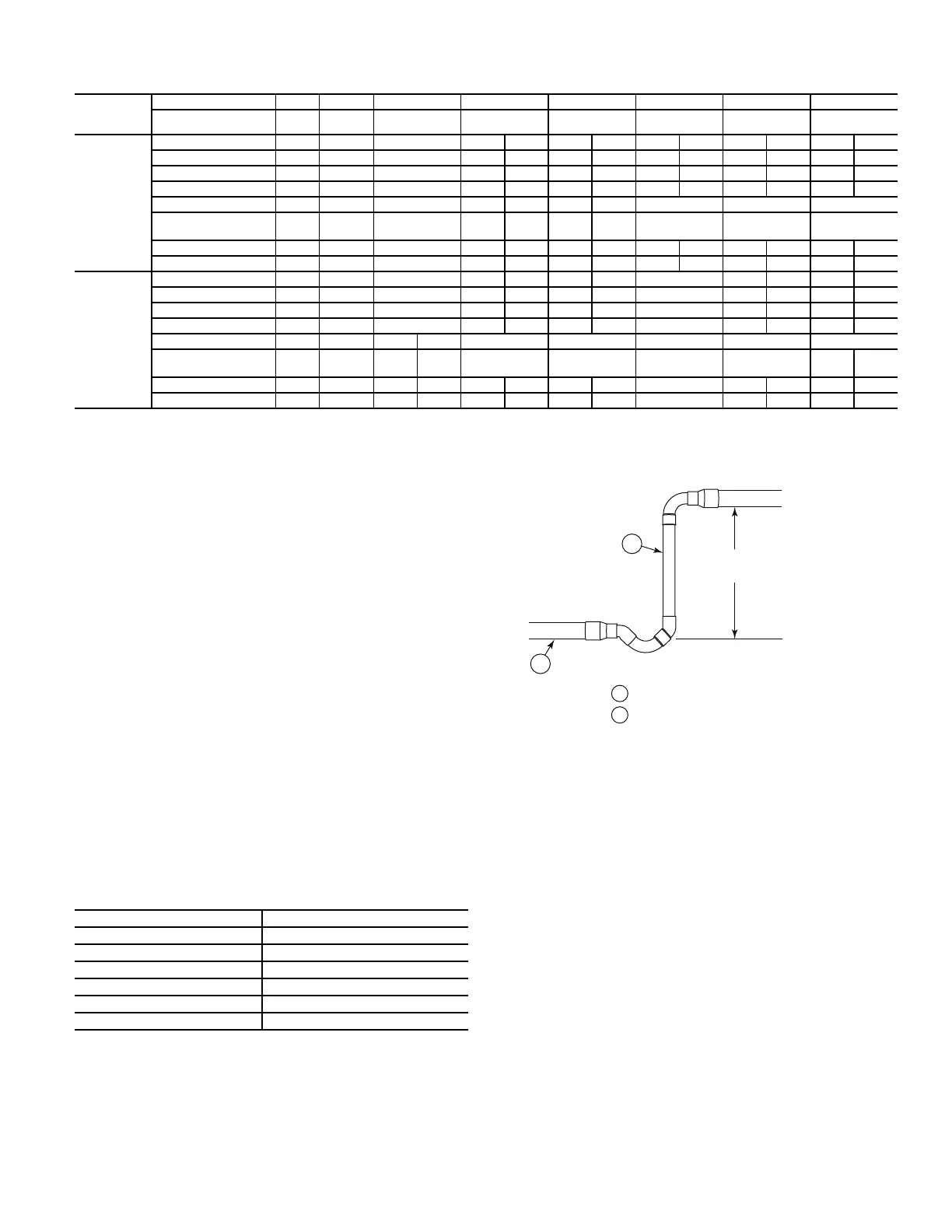
OUTDOOR UNIT ABOVE EVAPORATOR COIL
This installation will have at least one suction riser segment.
If the vertical elevation difference is less than 20 ft (6.1 m)
linear feet and requires only one or two segments, consider
a speed riser selection for Circuit 1; use the line marked VA-
POR RISER REQUIRED; NOT GREATER THAN 20 FT
(6.1 M). See Fig. 4. Tube S is the horizontal line size; tube A
is the reduced diameter riser size.
Fig. 4 — Suction Line Piping - Speed Riser
If the vertical elevation difference is greater than 20 ft
(6.1 m) linear feet or requires more than two short lift seg-
ments, select the Circuit 1 suction line size from Double
Suction Riser lines data under VAPOR RISER GREATER
THAN 20 FT (6.1 M). See Fig. 5. Tube S is the horizontal
line size. Tube A is the reduced diameter riser size without
bottom trap; Tube B is the parallel riser size with bottom oil
trap.
Outdoor Unit BELOW Evaporator Coil and No Verti-
cal Riser Segments
Select Circuit 1 suction line size from NO VAPOR RISER
line.
Vertical Separation (outdoor unit above indoor unit)
Vertical elevation difference of 200 ft (60 m) is permitted
when the outdoor unit (CAS072/091/121/151 or
CAS123/153) is located above the indoor unit.
Table 9 — CAS123/153 Piping Recommendations (Dual-Circuit)
a,b
a See Legend for Tables 8 and 9 on page 9.
b CAS123/153 units require TWO sets of refrigeration piping.
MODEL &
NOMINAL
CAPACITY
LINEAR LINE (FT) 0 - 24 25 - 49 50 - 74 75 - 99 100 - 124 125 - 149 150 - 174 175 - 200
EQUIV. LINE (FT) 0 - 37 38 - 74 75 - 112 113 - 149 150 - 187 188 - 224 225 - 262 263 - 300
C A S 1 2 3
TC 55.9
Each,
SC 12.7°F
Liquid Line Size (in.) 3/8 3/8 3/8 3/8 1/2 3/8 1/2 3/8 1/2 1/2 5/8 1/2 5/8
Liquid PD (°F) 1.4 2.7 5.5 5.5 0.9 6.9 1.1 8.2 1.4 1.6 0.5 1.8 0.5
Max Lift (ft) 25 50 75 82 100 66 125 49 133 130 144 128 144
Max Lift PD (F) 3.4 6.8 10.2 12.1 9.0 12.1 11.2 12.1 12.1 12.1 12.1 12.1 12.1
Suction Line Size (in.) 3/4 7/8 7/8 7/8 1-1/8 7/8 1-1/8 1-1/8 1-1/8 1-1/8
Suction Ln PD (F)
(Cap Red)
1.4 1.2 1.8
2 . 5
(-0.8%)
0.8
3 . 1
(-1.9%)
0.9 1.1 1.3 1.5
Charge (lb) 9.0 10.0 11.0 12.1 15.7 13.1 17.7 14.9 19.6 21.5 28.2 23.5 31.0
#/TR 0.73 0.81 0.89 0.97 1.27 1.05 1.42 1.20 1.58 1.74 2.27 1.89 2.50
C A S 1 5 3
TC 69.8
Each,
SC 14.2°F
Liquid Line Size (in.) 3/8 3/8 3/8 3/8 1/2 3/8 1/2 1/2 1/2 5/8 1/2 5/8
Liquid PD (°F) 2.1 4.1 6.2 8.2 1.5 10.3 1.8 2.2 2.6 0.7 2.9 0.8
Max Lift (ft) 25 50 75 69 155 42 125 145 140 163 135 162
Max Lift PD (F) 4.0 8.1 12.1 13.6 9.4 13.6 11.7 13.6 13.6 13.6 13.6 13.6
Suction Line Size (in.) 1-3/8
c
c AHRI ratings as listed are only valid with the piping diameters specified.
1-3/8
c
7/8 1-1/8 1-1/8 1-1/8 1-1/8 1-1/8 1-1/8
Suction Ln PD (F)
(Cap Red)
0.3 0.6
2 . 9
(-1.5%)
0.8 1.1 1.4 1.6 1.9
2 . 2
(-0.3%)
0.7
Charge (lb) 16.5 17.9 19.0 19.5 20.6 23.7 21.8 25.7 27.6 29.5 36.2 31.5 39.0
#/TR 1.44 1.56 1.52 1.56 1.65 1.90 1.74 2.05 2.21 2.36 2.89 2.52 3.12
LEGEND FOR TABLES 8 AND 9
#/TR —
Charge to unit capacity ratio, lbs per ton (at 45°F SST,
95°F ODA)
Cap Red —
Capacity reduction caused by suction line pressure
drop GT 2°F
Liquid PD (°F) — Liquid line pressure drop, saturated temperature, °F
Max Lift —
Maximum liquid lift (Indoor unit ABOVE outdoor unit
only), at maximum permitted pressure drop.
Max Lift PD (F) — Pressure drop including Maximum liquid lift value
SC — Sub-cooling, °F (at liquid line valve)
Table 10 — CAS Maximum Suction Pipe Size
MODEL AND UNIT SIZE MAXIMUM TUBE SIZE (in.)
CAS072 1-1/8
CAS091 1-1/8
CAS121 1-5/8
CAS151 2-1/8
CAS123 1-3/8
CAS153 1-5/8
Condensing
Unit
20-ft (6.1 m)
max
A
A - Suction Riser With Trap
LEGEND
S - Suction Line to Condensing Unit
S
 Loading...


