CAS-072-153-01SI Rev. A Specifications subject to change without notice. 35
APPENDIX A — AIR CONDITIONER AND HEAT PUMP WITH R-410A –
QUICK REFERENCE GUIDE
• R-410A refrigerant operates at 50 percent to 70 per-
cent higher pressures than R-22. Be sure that servic-
ing equipment and replacement components are de-
signed to operate with R-410A refrigerant.
• R-410A refrigerant cylinders are rose colored.
• Recovery cylinder service pressure rating must be
400 psig, DOT 4BA400 or DOT BW400.
• R-410A systems should be charged with liquid refrig-
erant. Use a commercial type metering device in the
manifold hose when charging into suction line with
compressor operating.
• Manifold sets should be 700 psig high side and
180 psig low side with 550 psig low-side retard.
• Use hoses with 700 psig service pressure rating.
• Leak detectors should be designed to detect HFC
refrigerant.
• R-410A, as with other HFCs, is only compatible with
POE oils.
• Vacuum pumps will not remove moisture from oil.
• Use only factory specified liquid-line filter driers with
rated working pressures greater than 600 psig.
• Do not install a suction-line filter drier in liquid-line.
• POE oils absorb moisture rapidly. Do not expose oil
to atmosphere.
• POE oils may cause damage to certain plastics and
roofing materials.
• Wrap all filter driers and service valves with wet cloth
when brazing.
• A factory approved, liquid-line filter drier is required
on every unit.
• Do not use an R-22 TXV.
• If indoor unit is equipped with a TXV, it must be
changed to an R-410A TXV.
• Never open system to atmosphere while it is under a
vacuum.
• When system must be opened for service, recover
refrigerant, break vacuum with dry nitrogen before
opening system.
• Always replace filter drier after opening system for
service.
• Do not vent R-410A refrigerant into the atmosphere.
• Do not use capillary tube coils.
• Observe all warnings, cautions, and bold text.
• All R-410A heat pumps must have indoor TXV.
• Do not leave R-410A suction line driers in place for
more than 72 hours.
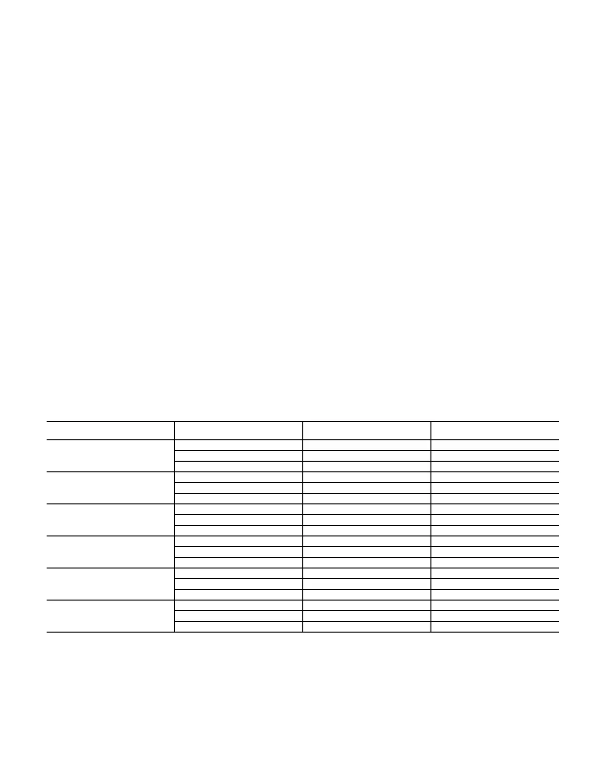
APPENDIX B — WIRING DIAGRAMS
UNIT
ELECTRICAL
CHARACTERISTICS
DIAGRAM NUMBER PAGE NUMBER
CAS072
208/230-3-60 38AU000441 36
460-3-60 38AU000441 36
575-3-60 38AU000442 37
CAS091
208/230-3-60 38AU000759 38
460-3-60 38AU000760 39
575-3-60 38AU000758 40
CAS121
208/230-3-60 38AU501323 41
460-3-60 38AU501322 42
575-3-60 38AU501324 43
CAS151
208/230-3-60 38AU501326 44
460-3-60 38AU501325 45
575-3-60 38AU501327 46
CAS123
208/230-3-60 38AU501320 47
460-3-60 38AU501319 48
575-3-60 38AU501321 49
CAS153
208/230-3-60 38AU501320 47
460-3-60 38AU501319 48
575-3-60 38AU501321 49



 To Next Page