8 Specifications subject to change without notice. CAS-072-153-01SI Rev. A
LIQUID LIFT
A liquid lift condition exists when the outdoor unit is located
below the indoor (evaporator) unit and liquid flows vertically
up in a portion of the liquid line. The vertical column of liquid
reduces the available state point sub-cooling at the evapo-
rator coil’s thermal expansion valve. This effect reduces the
length of liquid lift (feet of elevation) that a liquid line size can
accommodate. Longer linear tube lengths will also reduce
the amount of liquid lift possible.
Check Tables 8 (CAS072/091/121/151) and
9 (CAS123/153) for maximum liquid lift capabilities for
line sizes. Reselect the liquid line tube size if necessary.
If maximum available tube size cannot provide the re-
quired lift distance on this installation, relocate the out-
door unit to reduce the equivalent line length or the lift
requirement.
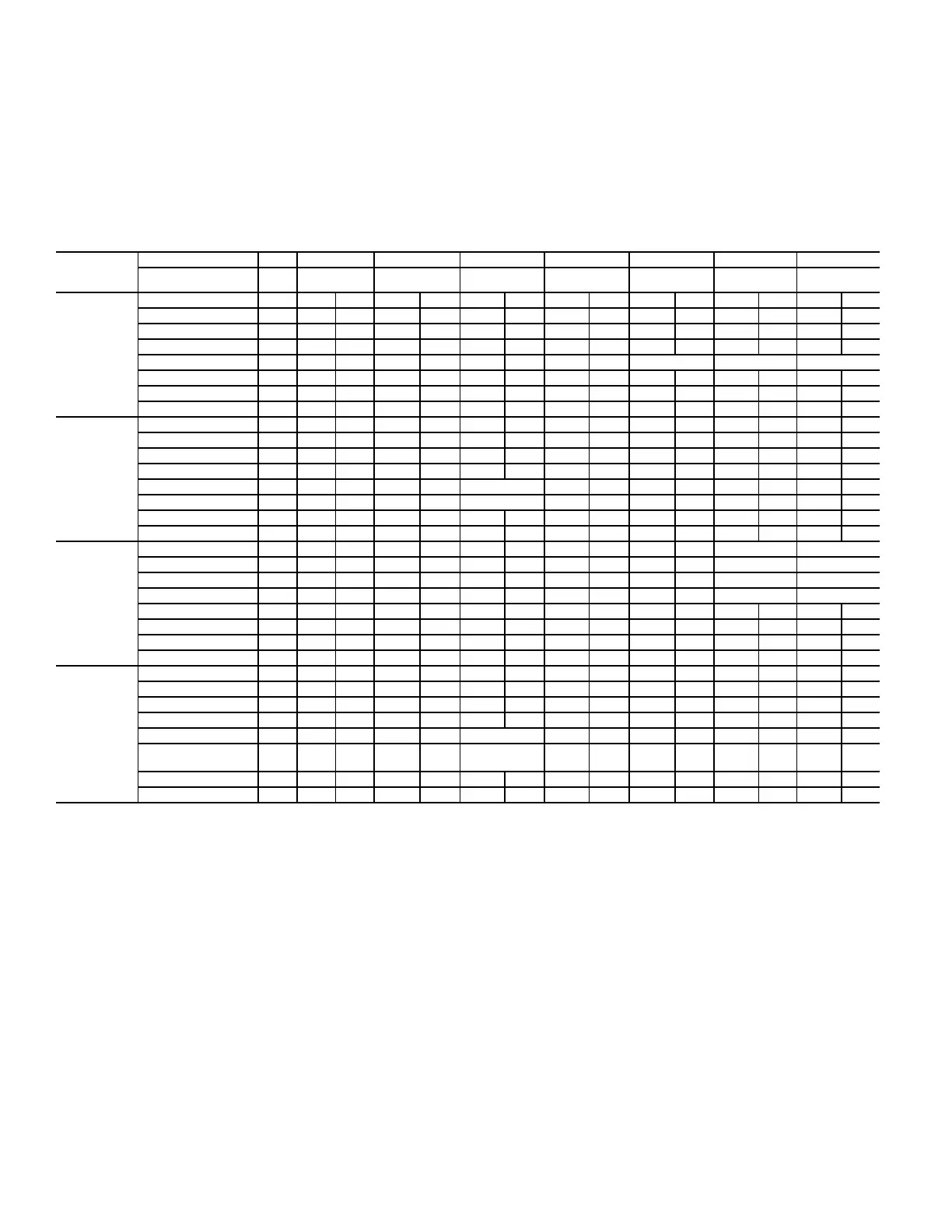
Table 8 — CAS072/091/121/151 Piping Recommendations (Single-Circuit)
a
MODEL &
NOMINAL
CAPACITY
LINEAR LINE (FT) 0 - 24 25 - 49 50 - 74 75 - 99 100 - 124 125 - 149 150 - 174 175 - 200
EQUIV. LINE (FT) 0 - 37 38 - 74 75 - 112 113 - 149 150 - 187 188 - 224 225 - 262 263 - 300
CA S0 72
TC 68.5,
SC 5.57°F
Liquid Line Size (in.) 3/8 3/8 1/2 1/2 5/8 1/2 5/8 1/2 5/8 1/2 5/8 1/2 5/8 1/2 5/8
Liquid PD (°F) 2.0 4.0 0.7 1.1 0.3 1.4 0.4 1.8 0.5 2.1 0.6 2.5 0.7 2.8 0.8
Max Lift (ft) 18734313944574157355431532752
Max Lift PD (F) 3.5 4.6 3.5 3.5 3.5 5.0 5.0 5.0 5.0 4.9 5.0 5.0 5.0 5.0 5.0
Suction Line Size (in.) 7/8 7/8 1-1/8 7/8 1-1/8 7/8 1-1/8 7/8 1-1/8 1-1/8 1-1/8 1-1/8
Suction Ln PD (F) 0.9 1.8 0.5 2.7 0.8 3.6 1.0 4.5 1.3 1.6 1.8 2.1
Charge (lb) 10.8 11.8 13.7 15.2 18.5 16.9 21.3 18.7 24.2 21.4 27.1 23.4 30.0 25.3 32.8
#/TR 1.90 2.07 2.41 2.67 3.25 2.97 3.74 3.28 4.25 3.8 4.75 4.1 5.26 4.4 5.75
C A S 0 9 1
TC 92.0,
SC 11.3°F
Liquid Line Size (in.) 1/2 1/2 5/8 1/2 5/8 1/2 5/8 1/2 5/8 1/2 5/8 1/2 5/8 1/2 5/8
Liquid PD (°F) 0.6 1.3 0.3 1.9 0.5 2.5 0.7 3.2 0.9 3.8 1.0 4.4 1.2 5.1 1.4
Max Lift (ft) 25 50 50 75 75 100 100 97 97 90 90 82 121 74 119
Max Lift PD (F) 2.7 5.4 4.5 8.1 6.7 10.8 9.0 11.2 8.9 11.2 8.5 11.2 11.2 11.2 11.2
Suction Line Size (in.) 7/8 7/8 1-1/8 7/8 1-1/8 1-1/8 1-1/8 1-3/8 1-1/8 1-3/8 1-1/8 1-3/8 1-1/8 1-3/8
Suction Ln PD (F) 1.5 3.1 0.8 4.6 1.2 1.6 2.1 0.7 2.5 0.8 2.9 1.0 3.3 1.1
Charge (lb) 15.6 19.0 19.7 20.8 24.1 23.1 26.9 25.1 30.7 26.0 32.8 27.0 34.8 27.9 37.1
#/TR 2.08 2.53 2.63 2.77 3.21 3.08 3.59 3.35 4.09 3.47 4.37 3.60 4.64 3.73 4.95
C A S 1 2 1
TC 113.1,
SC 7.1°F
Liquid Line Size (in.) 1/2 1/2 5/8 1/2 5/8 1/2 5/8 1/2 5/8 1/2 5/8 5/8 5/8
Liquid PD (°F) 0.9 1.9 0.5 2.8 0.8 3.8 1.0 4.7 1.3 5.7 1.6 1.8 2.1
Max Lift (ft) 25 40 50 28 54 34 68 22 65 11 63 59 55
Max Lift PD (F) 2.9 5.0 4.5 5.0 5.0 6.5 6.4 6.5 6.4 6.5 6.5 6.4 6.4
Suction Line Size (in.) 7/8 1-3/8 1-3/8 1-1/8 1-3/8 1-1/8 1-3/8 1-1/8 1-3/8 1-1/8 1-3/8 1-1/8 1-3/8 1-1/8 1-3/8
Suction Ln PD (F) 2.4 1.2 1.2 1.8 0.6 2.4 0.9 3.1 1.1 3.7 1.3 4.3 1.5 4.9 1.7
Charge (lb) 15.7 18.0 20.0 19.8 23.1 21.6 26.1 23.6 29.2 25.5 32.3 34.1 35.3 36.9 38.4
#/TR 1.67 1.89 2.09 2.10 2.45 2.29 2.77 2.50 3.10 2.71 3.43 3.62 3.75 3.92 4.08
C A S 1 5 1
TC 146.1,
SC 3.9°F
Liquid Line Size (in.) 5/8 5/8 3/4 5/8 3/4 5/8 3/4 5/8 3/4 5/8 3/4 5/8 3/4 3/4 7/8
Liquid PD (°F) 0.4 0.8 0.4 1.2 0.6 1.6 0.8 2.0 1.1 2.4 1.1 2.8 1.5 1.7 0.6
Max Lift (ft) 23 16 23 10 18 28 38 21 36 14 35 9 30 25 43
Max Lift PD (F) 1.8 1.84 1.84 1.8 1.8 3.3 3.3 3.3 3.3 3.3 3.3 3.3 3.3 3.3 3.3
Suction Line Size (in.) 1-5/8
b
1-5/8
b
1-5/8
b
1-1/8 1-3/8 1-3/8 1-3/8 1-5/8 1-3/8 1-5/8 1-3/8 1-5/8 1-3/8 1-5/8
Suction Ln PD (F)
(Cap Red)
0.1 0.2 0.2
3 . 3
(–2.3%)
1.2 1.6 2.0 0.8
2 . 4
(–0.7%)
1.0
2 . 8
(–1.4%)
1.2
3 . 2
(–2.1%)
1.3
Charge (lb) 35.1 38.4 40.9 37.6 41.8 41.1 46.1 44.2 51.6 47.3 56.1 50.3 60.6 63.4 76.9
#/TR 3.10 3.99 3.62 3.09 3.44 3.38 3.79 3.64 4.24 3.89 4.61 4.14 4.98 5.21 6.32
a See Legend for Tables 8 and 9 on page 9.
b AHRI ratings as listed are only valid with the piping diameters specified.
 Loading...


