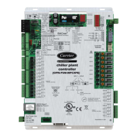
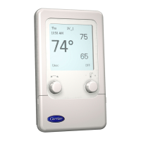
2 - COMPOSITION
■ Designation of terminals
EA = Analogue inputs
EL = Logic inputs
SA = Analogue outputs
SL = Logic outputs
TERMINAL CCU Controller
J1
(EA)
1 Target temperature sensor (10 K Ω)
2 0 V
3 Supply air limit temperature sensor (10 K Ω)
4 Target relative humidity sensor (0 - 10 V)
5 0 V
6 Sensor for controlling the dierential pressure on the lter (0-10 V or 0,5 - 4,5 V)
7 +12 V
J2
(EL)
1 Remote control
2 Fire detection/External safety
3 Supply air fan operation feedback
4 Electric heater safety thermostat with manual reset
5 Humidier fault or maintenance
6 Water leak
7 Logic input common terminal
J3
(EL)
1 Summary of condensation unit circuit 1 faults
2 Temperature setpoint shift
3 Summary of condensation unit circuit 2 faults
4 Hot water coil or electric heater
6 Summer or winter mode
7 Logic input common terminal
J4
(SA)
1 Hot water coil three-way valve
2 0 V
3 Chilled water coil or mixed coil three-way valve
4 Progressive humidier
5 0 V
6 Variation of the air ow rate
7 Free cooling damper
8 0 V
9 Electric heater (TRIAC)
J5
(SL)
1 Critical fault summary common terminal
2 Standby contact if P206=0 (or active if P206=1) in the summary of major faults
3 Active contact if P206=0 (or standby if P206=1) in the summary of major faults
4 Non-critical fault summary common terminal
5 Standby contact if P205=0 (or standby if P205=1) in the summary of minor faults
6 Active contact if P205=0 (or standby if P205=1) in the summary of minor faults
J6
(SL)
1 Condensation unit 1 control
2
3 Refrigerating stage no. 1 common terminal
4 Condensation unit 2 control
5
6 Refrigerating stage no. 2 common terminal
7
 Loading...


