2 - COMPOSITION
NOTE: The text that follows the unit number indicates its operating status.
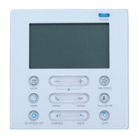
The rst line is simply a display of the date and time. We can access this main menu via the "0" number key from any of the displays.
Move the cursor opposite the line corresponding to the required information using the cursor pad, then hit "ENTER".
The "CONFIGURATION OF NUMBER OF UNITS"’ line is used to congure the operation of the units connected to the bus.
The "UNIT…" lines are used to query the machine.
To return to the main menu, press the number key "0" several times.
■ Locking the keypad
The control can be locked or unlocked by pressing the “right arrow” and “left arrow” keys simultaneously for 5 seconds.
When the controller is locked, the user can view the information but cannot edit the settings.
2.2 - On the rear:
The various connectors used to connect the various elements required to control the unit.
■ INPUTS
- On/o:
• Acquisition of states via the traditional electro-mechanical components.
- Analogue:
• Acquisition of temperatures via a thermistor type sensor.
• Acquisition of relative humidities via sensors delivering a voltage varying from 0 to 10 V for relative humidity of 0 to 100 %.
• Acquisition of dierential pressures in the air on the lter via a sensor delivering a voltage varying from 0 to 10 V or from 0.5 to
4.5 V for 0 to 1000 Pa.
• Acquisition of dierential pressures in the air on the fan (enabling ow rate calculation) via a sensor delivering a voltage varying
from 0 to 10 V for 0 to 2500 Pa
■ OUTPUTS
- On/o:
• Fan control.
• Stage control of compressors and electric coils.
• Critical and non-critical fault summary changeover contacts.
- Analogue:
• Control of the three-way valves for the water coils and the electric heater current valve.
• Control of the progressive humidier.
• Control of the fan speed controller.
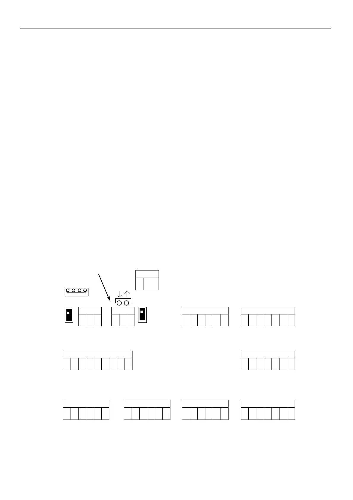
LOCATION OF TERMINALS (main board)
J1
1 23456
1 23456
123456
J2
1234567
J4
89
1 23456
J15
123
J9
123
J10J10
123
J8
COM1COM2
J14
OFF
ON
ON
Communication LED
6