Do you have a question about the Carrier CCU and is the answer not in the manual?
Checks filter pressure drop by monitoring air flow and fouling level.
Manages cooling, heating, dehumidification, and humidification based on environmental conditions.
Manages fan operation and faults for single or variable speed fans.
Covers overheating, pressure sensors, alarm thresholds, and water leak detection.
Stores faults and settings; enables remote unit operation.
Displays operating hours, compressor starts, and fault summaries.
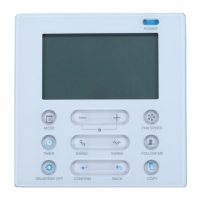
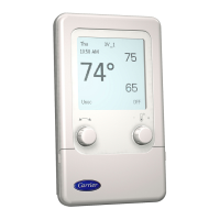
Describes the human-machine interface, display, buttons, and their functions.
Lists and details components like LCD screen, push buttons, cursor, and number pad.
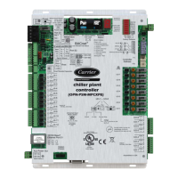
Details connectors for input/output signals and external components.
Describes On/off and Analogue inputs/outputs for sensors and controls.
Visual representation of terminal block layout on the main board.
Explains terminal designations like EA, EL, SA, SL.
Detailed list of terminal assignments for J1, J2, J3, J4, J5, J6.
Continues terminal assignments for J7, J8, J9, J10, J14, J15.
Settings for COM1 termination resistance and COM2 bus polarization.
Covers battery replacement, hazards, safety guidelines, and recycling.
Navigational paths for configuring unit quantity and master/slave operation.
Overview of menus for accessing unit operating info, faults, and parameters.
Detailed unit menus and overview of parameter sub-menus.
Programming ventilation and setpoint shifts using timer channels.
Configuring fault forwarding to critical or non-critical relays.
Settings for communication protocols and parameters.
Managing user access levels for configuration and operation.
Settings, readings, and alarms for the humidifier component.
Parameters and information related to supply air fans.
General user level for reading parameters and main settings.
Installer/experienced user level for advanced functionalities.
Manufacturer/factory level for all control parameters.
Settings for operating configuration, unit parameters, and read-only counters.
Visual flowchart for configuring unit numbers and related settings.
Overview and configuration of unit parameters, including unit type.
Parameters related to fan control and speed variation.
Options for cooling, heating, and humidification control types.
Settings for heating, dehumidification, humidification, and free cooling.
Parameters for exchangers, modes, air flow, and pressure controls.
Settings for electric heater power and fan speed control limitations.
Parameters for return/supply air temperature differential and proportional band.
Parameter P99 for locking/unlocking unit configuration.
In-depth settings for cooling, heating, humidification, dehumidification.
Settings for downward shift and proportional band for cooling demand reduction.
Parameters for free cooling and supply air temperature limitations.
Settings for setpoint shifts and air flow rate control parameters.
Settings for floor pressure control and fan speed limitations.
Parameters for return/supply air temperature differential and proportional band.
Settings for filter differential pressure and air flow low limit.
Parameters for compressor validation and various time delay settings.
Upper and lower limit thresholds for temperature and humidity.
Settings for test mode, fault relay action, and temperature source selection.
Settings for 2-10V sensors and master/slave bus unit addressing.
Access to calculated setpoints, measured values, and logic input states.
Displays measured values and the status of logic inputs.
Displays percentages for analogue outputs and status of compressors, heaters, fans.
Shows fault summary status, fan request, and temperature setpoint shift status.
Information on time delays, software version, measured temperatures, and order numbers.
Configuration parameters and settings for the humidifier.
Reading parameters for humidifier outdoor request, steam flow, and conductivity.
Lists humidifier alarms, their causes, and fault acknowledgement.
Configuration parameters for supply air fan information.
Detailed information for FMA1 parameters.
Detailed information for FMA2 parameters.
Detailed information for FMA3 parameters.
Configuring fault forwarding to critical or non-critical relays.
Table listing faults, sources, causes, and recommended solutions.
Notes on how specific faults affect machine shutdown and operation.
Introduction to programmable timer channels for weekly scheduling.
Programming ventilation activation and setpoint shifts via timer channels.
Step-by-step guide for setting up weekly programs with times and days.
Explanation of proportional and proportional-integral control principles.
Explanation of proportional and proportional-integral control principles.
How staged control is triggered based on measured value deviations.
How target temperature is controlled in cooling and heating modes.
How target relative humidity is controlled in dehumidification and humidification.
Specifications and adjustment for NTC temperature sensors.
Specifications and adjustment for NTC temperature sensors.
Specifications for 2-10V sensors and fault handling.
Specifications and adjustment for humidity sensors.
Specifications for filter and fan differential pressure sensors.
Procedures for powering up and performing initial adjustments.
Procedures for powering up and performing initial adjustments.
Explains various operating statuses for units in master/slave configurations.
Details displayed for unit status, faults, and measurements.
Lists faults, sources, causes, and solutions for troubleshooting.
Continues the alarm table for temperature and humidity related issues.
Diagram showing bus connection between CCU controllers.
Diagram showing bus connection between CCU controllers.
Steps to address units in a master/slave configuration.
Diagram illustrating the RS485 Modbus CMS bus connection.
Diagram illustrating the RS485 Modbus CMS bus connection.
Parameters for communication mode, speed, parity, and stop bits.
Information on RS485 communication, transmission, protocol, and function codes.
Table mapping ModBus registers to controller parameters and their ranges.
Continues mapping ModBus registers for operation status and faults.
Information on Modbus to BACnet gateways and associated responsibilities.
Information on Modbus to BACnet gateways and associated responsibilities.
Connection diagrams for Modbus, BACnet MSTP, and BACnet IP interfaces.
Configuration parameters for ModBus communication with controllers.
Configuration parameters for ModBus communication with controllers.
Specifications for BACnet IP gateway configuration and object publication.
Specifications for BACnet MSTP gateway configuration and object publication.
Table of ModBus registers and BACnet objects accessible to customers.
| Brand | Carrier |
|---|---|
| Model | CCU |
| Category | Controller |
| Language | English |