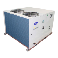
Table – 2 Unit Weights and Dimensions
NOTES:
1. Remove boards at ends of unit and runners prior to rigging.
2. Rig by inserting hooks into unit base rails as shown. Use bumper boards for spreader bars.
2.4 – Positioning and Clearance.
Before positioning the unit, check the following:
• The permitted loading at the site is adequate or that appropriate strengthening measures have been taken.
• The unit is installed level on an even surface (maximum tolerance is 5 mm in both axes).
• Ensure access to the components (see “Unit Dimensional Drawings” Fig 1 & 2 & “Clearance Diagram” Fig 3).
• The number of support points is adequate and that they are in the right places.
• Although the unit is weatherproof guard against water from higher level runoff and overhangs.
Unit may be installed directly on wood flooring or on approved roof - covering material when roof curb is used. Do not
install unit in an indoor location. Do not locate air inlets near exhaust vents or sources of contaminated air.
2.5 – Field Fabricate Ductwork
Secure all ducts to building structure. Use flexible duct connectors between unit and ducts as required (a space for 2.5
to 3ft is required in case of repairing or replacing the blower wheel). Insulate and weatherproof all external ductwork,
joints, and roof openings with counter flashing and mastic in accordance with applicable codes. Ducts passing through
an unconditioned space must be insulated and covered with a vapor barrier.
The 50TJM units with electric heat require a 2-in.clearance for the first 24-in. of ductwork. Outlet grilles must not lie
directly below unit discharge.
2.6 – Make Unit Duct Connections
Unit is shipped for side duct connections. Ductwork openings are shown in Fig. 1 and Fig. 2.
UNIT
SHIPPING DIMENSIONS
SHIPPING
UNIT DIMENSIONS (mm) UNIT WEIGHT
A 90-degree elbow must be provided in drain hole and must be removed in ductwork to comply with UL
(Underwriters’ Laboratories) codes for use with electric heat.
All units are internally isolated against vibration.
If extra isolation required, please see “Unit
Dimensional Drawing” Fig - 1 and Fig - 2 for
Failure to follow this caution may result in
equipment damage.
All panels must be in place when rigging.

 Loading...