DLFSOAH: Installation Instructions
Manufacturer reserves the right to change, at any time, specifications and designs without notice and without obligations.
16
Step 5 - Panel Installation - Ceiling Prep
Use the following steps to prepare the ceiling.
1. Drill a 16.93”x51.18” (430 mm x 1300 mm) hole into the ceiling based
on the layout of the installation board. The center of the ceiling opening
should match the center of the body of the indoor unit.
NOTE: To prevent vibrations, reinforce the ceiling where necessary.
2. Once the ceiling is cut, remove the installation board.
Step 6 - Panel Installation
Model A
NOTE: The air grille received by the customer is not tightened by the
wire rope, however is specifically designed to be loose for
easy installation.
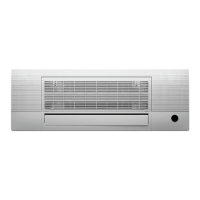
1. Grab air grille by hand and pull it out slowly in the direction of the
arrow.
Fig. 31 — Panel Installation
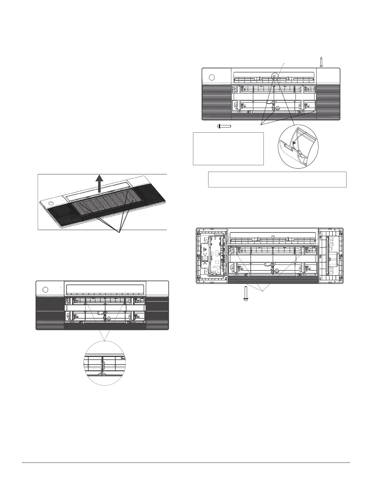
2. Pull the panel grille out of the panel, secure the cassette panel to the
one-way cassette with the two plastic straps.
Fig. 32 — Panel Installation
3. Manually rotate the louver, secure the panel to the cassette with
3×M4*22 screws and a ST3.9*16 screw.
Fig. 33 — Panel Installation
4. Open the two covers on both sides of the panel and secure the panel to
the cassette with 3× M4*22 screws.
Fig. 34 — Panel Installation
5. Connect the display board to the main control board, up to four wires
are required to connect.
Grab at these locations
Before securing the screw, open the screw cover.
After securing the screw, close the cover.
NOTE
Eight M4*22 screws are supplied,
two of which are spares.
Two ST3.9*16 screws are supplied,
one of which is a spare.
M4*22 screw
ST3.9*16 screw