DLFSOAH: Installation Instructions
Manufacturer reserves the right to change, at any time, specifications and designs without notice and without obligations.
17
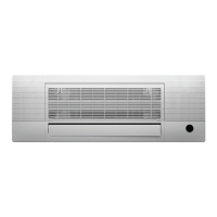
NOTE: The corresponding colors or pins are connected to each other.
Fig. 35 — Panel Installation
6. Install the control box cover and turn the disconnect switch to ON, then
close the two plastic covers on both sides of the panel.
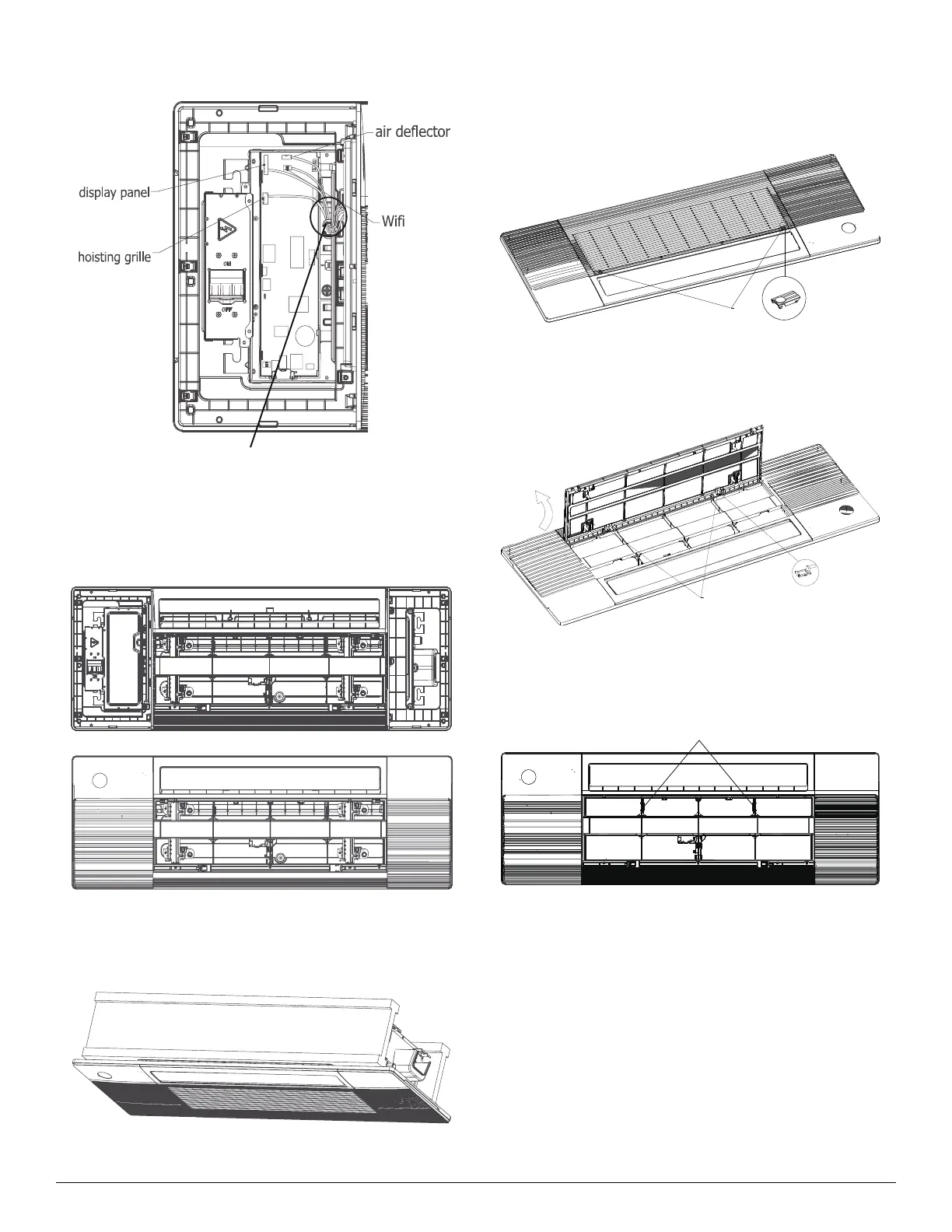
Fig. 36 — Panel Installation
7. During the test-run process, the display illuminates and the air grille
raises automatically.
Fig. 37 — Panel Installation
Model B
1. Press the circular position to open the two screw covers, then remove
the two screws.
Fig. 38 — Panel Installation
2. Hold and open the air grille, then push both latches to the middle to
unlock the air grille.
Fig. 39 — Panel Installation
3. Remove the panel grille from the panel, secure the cassette panel to the
one-way cassette with the two plastic straps.
Fig. 40 — Panel Installation
when the connection is complete,
cli
the wires to the stra
.
(white 10-core)
(white 5-core)
plastic strap