DLFSOAH: Installation Instructions
Manufacturer reserves the right to change, at any time, specifications and designs without notice and without obligations.
18
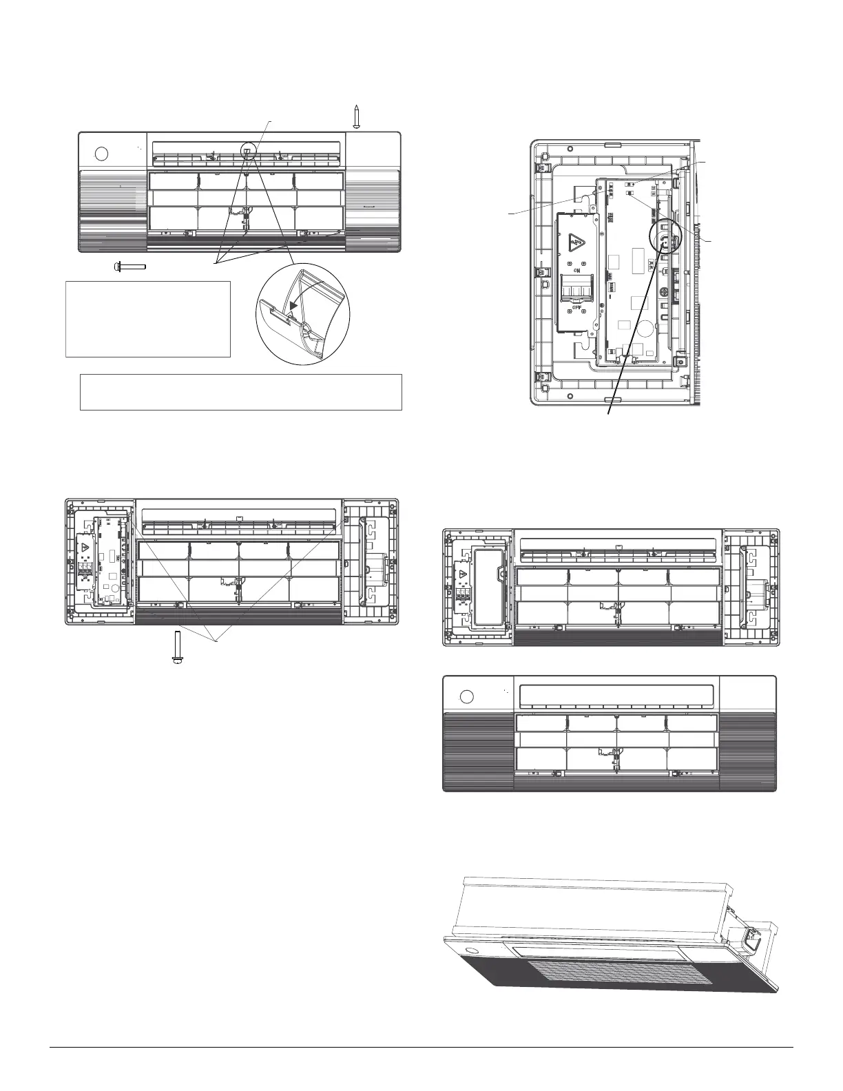
4. Manually rotate the louver, secure the panel to the cassette with
3×M4*22 screws and a ST3.9*16 screw.
Fig. 41 — Panel Installation
5. Open the two covers on both sides of the panel, secure the panel to the
cassette with 3× M4*22 screws.
Fig. 42 — Panel Installation
6. Connect the display board to the main control board, up to four wires
are required to make the connection.
NOTE: The corresponding colors are corresponding pins are
connected to each other.
Fig. 43 — Panel Installation
7. Install the control box cover and set the disconnect switch to ON, then
close the two plastic covers on both sides of the panel.
Fig. 44 — Panel Installation
8. Re-install the air grille by pushing the latches to lock it and secure the
two screws, then close the two screw covers.
Fig. 45 — Panel Installation
Before securing the screw, open the screw cover.
After securing the screw, close the cover.
NOTE:
Eight M4*22 screws are supplied,
two of which are spares.
Two ST3.9*16 screws are supplied,
one of which is a spare.
M4*22 screw
ST3.9*16 screw
display panel
(white 10-core)
louver
(white 5-core)
Wi
(4 core)
when the connection is complete, clip
the wires to the strap.