Evaporator A-Coil, Cased, Multipoise for R-454B Refrigerant: Installation Instructions
Manufacturer reserves the right to change, at any time, specifications and designs without notice and without obligations.
5
Refrigerant Line Connections
NOTE: Factory nitrogen charge may escape past rubber plugs during
storage. This does not indicate a leaking coil nor warrant return of the
coil.
Size and install refrigerant lines according to information provided with
outdoor unit. Coil connection tube sizes are shown in the Product Data
sheet. Route refrigerant lines to the coil in a manner that will not obstruct
service access to the unit or removal of the filter.
Do not use damaged, dirty, or contaminated tubing because it may plug
refrigerant flow-control device. ALWAYS evacuate the coil and
field-supplied tubing before opening outdoor unit service valves.
Connect Refrigerant, Liquid, and Suction Lines
For matched and mismatched systems, use line sizes recommended in
outdoor unit Installation Instructions.
Mechanical Fittings
IMPORTANT: Mechanical fittings must meet or exceed maximum
operating pressure of 700 psig for evaporator coils.
Follow mechanical fitting supplier's instructions for installation.
Brazed Fittings
The coil can be connected to outdoor units using field-supplied tubing of
refrigerant grade. Always evacuate tubing and reclaim refrigerant when
making connections or flaring tubing. Leak check connections before
insulating entire suction line.
See Table 1 for coil connection tube size.
1. Remove cabinet access door.
2. Remove rubber plugs, suction plug then liquid plug, from coil stubs
using a pulling and twisting motion. Hold coil stubs steady to avoid
bending or distorting.
3. Remove fitting door with rubber grommets and slide fitting door
with grommets onto the refrigerant lines (field line-set), away from
braze joints.
4. For optimal performance, swedge stub outs according to the
outdoor unit’s recommended lineset size. Wrap a heat sinking
material such as a wet cloth behind braze joints.
5. Wrap TXV and nearby tubing with a heat-sinking material such as a
wet cloth.
6. Use 1/2 psig Nitrogen purge in the suction and out the liquid line.
7. Braze using a Sil-Fos or Phos-copper alloy. Do not use soft solder.
8. After brazing, allow joints to cool. Carefully remove TXV bulb
insulation and verify that the TXV bulb is securely fastened with
hose clamp. Tighten screw a half-turn past hand tight with TXV
bulb placed in the indentation with full contact with the vapor line
tube. Re-wrap TXV bulb with insulation.
9. Perform a pressure check of the unit with a nitrogen charge of
approx. 200psi. The nitrogen holding charge must not decrease in
pressure for 1 hour.
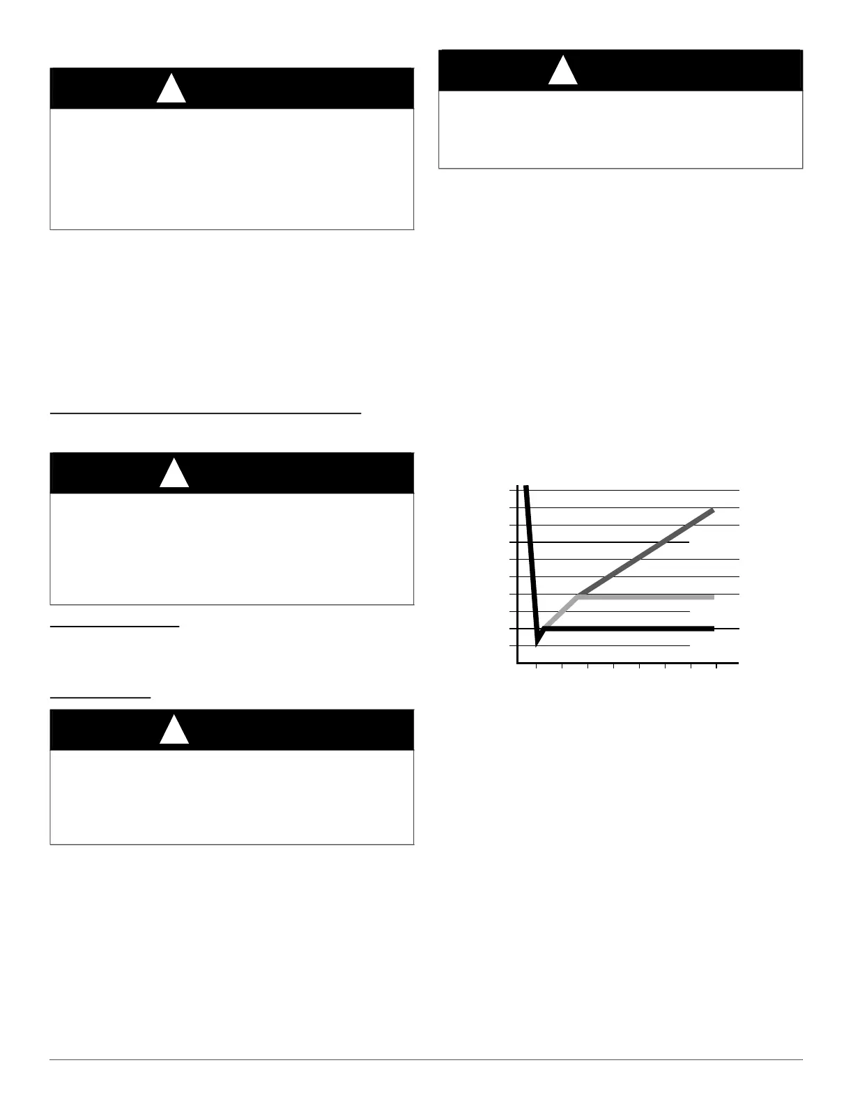
10. Perform a leak check on the unit. Vacuum unit to 500 microns.
When isolating the unit from the pump, the pressure shall not rise
above 1000 microns in 7 minutes (Fig. 10).
A95424
Fig. 10 – Deep Vacuum Graph
11. Slide fitting door with rubber grommets over joints. Position tubing
at center of each grommet to ensure an air seal around the tube.
Reinstall cabinet door.
TXV
NOTE: These TXV’s are equipped with mechanical connections. There
is no brazing required.
A thermal expansion valve is utilized in this coil design to optimize
performance and comfort throughout the entire cooling operating range
of the system. Special attention needs to be taken to the TXV when
installing the coil (Fig. 11):
• Place liquid filter dryer near indoor unit to reduce the risk of debris
clogging the valve.
• Make sure TXV bulb is securely fastened with a metal strap and
wrapped in the indentation on vapor line tube.
These specific coils have a factory-installed hard-shutoff TXV designed
only for use with R-454B refrigerant. Use only with outdoor units
designed for R-454B refrigerant.
NOTE: These TXV’s are factory set at approximately 10° superheat
measured at the suction service valve, and are not field adjustable.
WARNING
!
PERSONAL INJURY HAZARD
Failure to follow this warning could result in personal injury.
Wear eye protection.
Coil is factory charged with 15 psi nitrogen. The coil is under pressure
and TXV screen is in place behind liquid line plug. DO NOT remove
liquid line plug first, always remove the suction line plug first to
depressurize the coil.
CAUTION
!
UNIT OR PRODUCT DAMAGE HAZARD
Failure to follow this caution may result in property damage.
Take precautions to ensure Aluminum tubes do not come in direct
contact or allow for condensate run off with a dissimilar metal.
Dissimilar metals can cause galvanic corrosion and possible premature
failure.
CAUTION
!
UNIT DAMAGE HAZARD
Failure to follow this caution may result in product damage.
To avoid valve damage to the refrigerant control device while brazing,
valves must be wrapped with a heat-sinking material such as a wet
cloth.
CAUTION
!
UNIT DAMAGE HAZARD
Failure to follow this caution may result in damage.
All aluminum tubing and coils must be adequately shielded from any
copper braze splatter.
500
MINUTES
01234 56 7
1000
1500
LEAK IN
SYSTEM
VACUUM TIGHT
TOO WET
TIGHT
DRY SYSTEM
2000
MICRONS
2500
3000
3500
4000
4500
5000