Evaporator A-Coil, Cased, Multipoise for R-454B Refrigerant: Installation Instructions
Manufacturer reserves the right to change, at any time, specifications and designs without notice and without obligations.
9
A230461
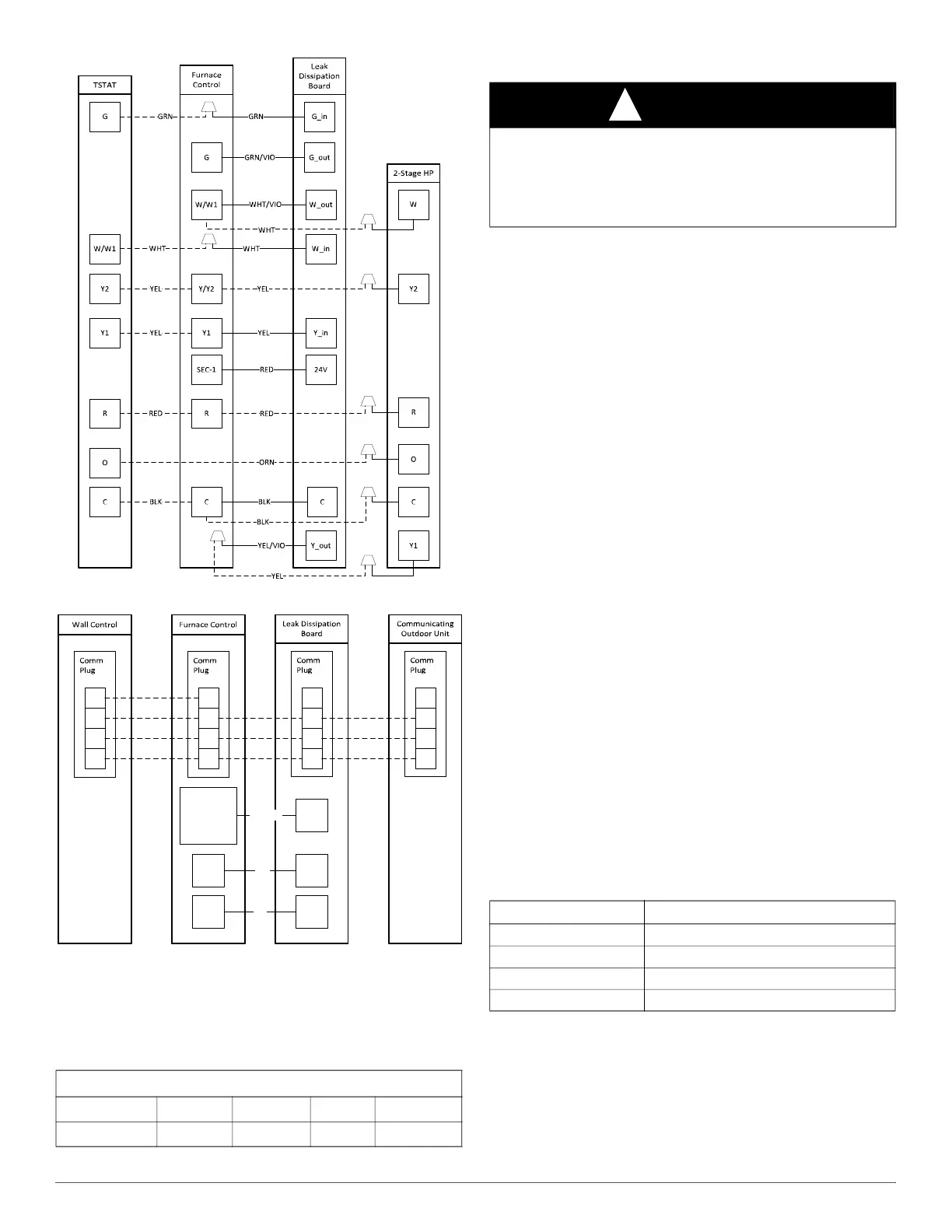
Fig. 22 – Wiring Layout, 2-Stage Heat Pump Unit
A240005
Fig. 23 – Wiring Layout, Communication Unit
Leak Dissipation System Installation
1. After installing evaporator coil and line set, route the sensor cable
through the liquid grommet on the fitting door. Ensure that the wire
harness has tension relief and does not come into contact with sharp
edges.
2. Mount the dissipation board assembly (control board, enclosure
bottom, and enclosure top) as close as possible to the furnace
control box.
If drilling, check behind the drill location where mounting the
dissipation board assembly to ensure no damage to hidden electrical
or mechanical components.
Mount enclosure in a vertical orientation with the harnesses coming
out of the bottom, in a location that is easily accessible, and
indicator light is visible.
a. Do NOT mount control board assembly in a location where it
could come into contact with or be exposed to water.
b. Do NOT mount control board assembly inside of evaporator coil,
furnace, or ductwork.
3. Remove control board housing cover and plug in sensor wire
harness (4-pin connector) and power wire harness (8-pin connector)
to the dissipation control board.
4. Route control board power harness (8 wires) to the furnace control
box and make all connections according to wiring diagrams and
wiring label.
5. Power on unit and verify proper functioning of equipment. Yellow
LED on control board should be steady. If flash codes are present,
see the troubleshooting section.
NOTE: For communicating systems, green LED should be on (steady or
flashing).
IMPORTANT: Press the Test button for approximately ONE SECOND
to enter Test Mode. Pressing the Test button for a longer period can
possibly clear all fault code history.
6. Press the Test button on the dissipation system control board to
ensure proper dissipation system operation under each test
condition listed below (Table 5). After pressing the test button,
system will enter dissipation mode for 60 seconds to help verify
correct operation.
7. Ensure that the furnace is able to meet the minimum required
dissipation mode airflows. These required minimum airflow rates
during dissipation mode are listed in Table 6. They are based on the
total system refrigerant charge quantity.
If the minimum airflow is not achievable by energizing the continuous
fan (G terminal), an accessory kit is available to achieve cooling airflow
in dissipation mode. Refer to the Accessories section of the Product Data
for current kit number.
Table 3 – Communication Plug Designations
CCN Plug Connections
Color
GRN YEL WHT RED
Signal
DX+ DX- C NO USE
NOTE: Dissipation terminal is only used on communicating furnaces
manufactured Q4 2023 and later. Use a 3/16” spade connector on the
GRN/VIO wire to connect to the dissipation terminal on communicating
furnaces. Attach wire nut to all unused wires from the power harness.
C
SEC-1 RED 24V
CBLK
Dissipation
Terminal*
G_outGRN/VIO
DX+
DX-
C
R
DX+
DX-
C
R
DX+
DX-
C
NO
USE
DX+
DX-
C
NO
USE
WARNING
!
PERSONAL INJURY HAZARD
Failure to follow this warning could result in property damage, personal
injury, or death.
Operational checks to confirm proper dissipation system function must
be performed prior to normal operation of the system.
Table 4 – Dissipation Board Test Button Functions
Hold Button Time (sec) Function
1 - 4 Dissipation Mode for 60 seconds
5 - 29 Display flash code history
30+ Flash code 6
3 rapid presses Clear flash code history