Evaporator A-Coil, Cased, Multipoise for R-454B Refrigerant: Installation Instructions
Manufacturer reserves the right to change, at any time, specifications and designs without notice and without obligations.
7
IMPORTANT: Sensor must be installed with the connector facing
down or facing horizontally. Sensor should never be positioned with
connector facing upward. Incorrect sensor position could result in
premature failure.
A230510
Fig. 14 – R-454B Leak Sensor Mounting Location
(all A-Coil Applications)
Sensor Wire Harness
The 8-foot-long sensor wire harness will be factory installed to the
sensor inside of the evaporator coil. Verify that the sensor wire harness is
connected to the refrigerant sensor (Fig. 14).
A230454
Fig. 15 – Sensor Wire Harness Pin Layout
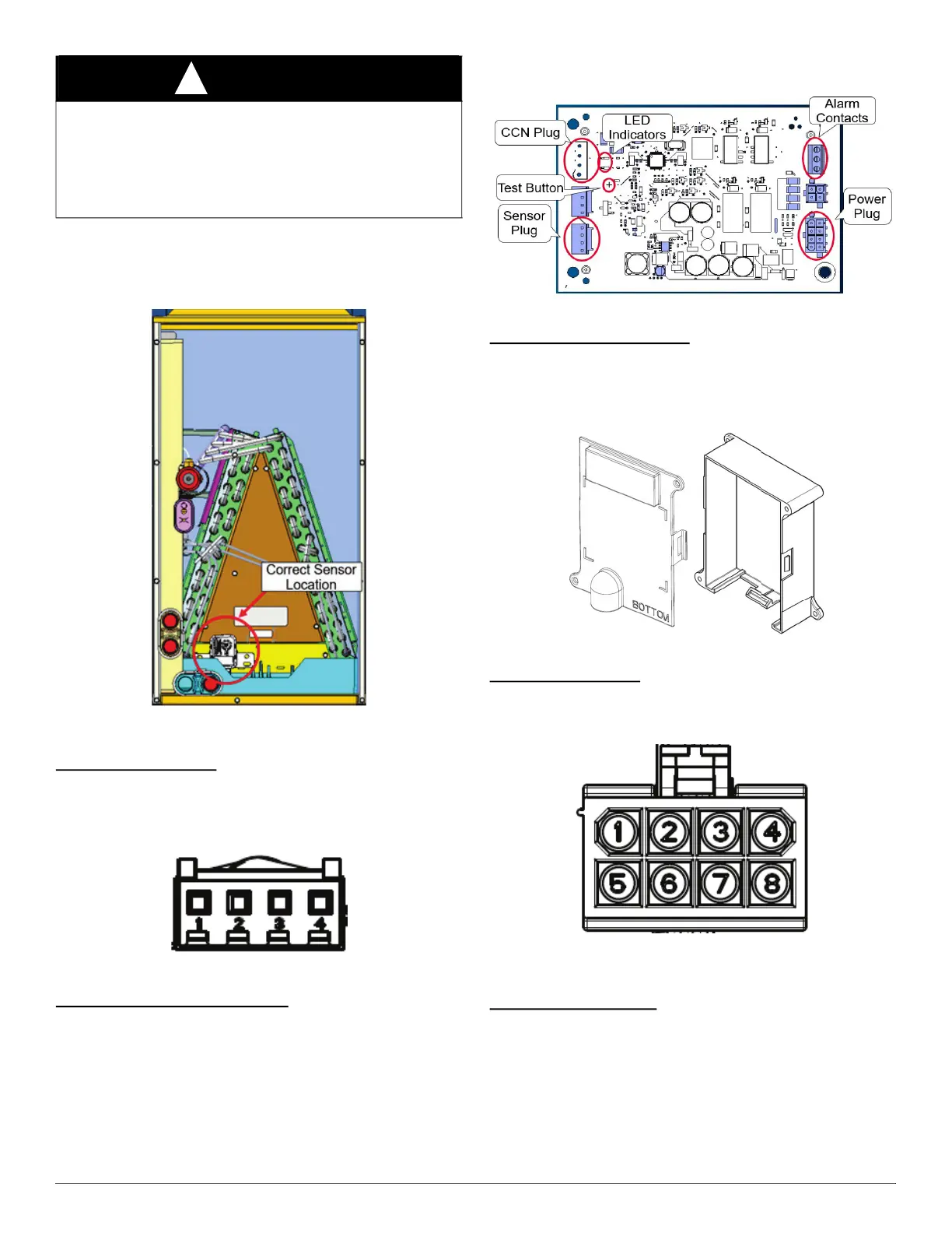
Leak Dissipation Control Board
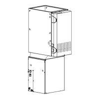
The leak dissipation control board will be factory installed inside of the
dissipation board housing (Fig. 16, Fig. 17).
The dissipation board housing cover is clear, so the LED indicators can
be viewed when servicing (Fig. 17). There are two LED indicators: one
amber for system status; one green for communicating systems only.
NOTE: The Communicating (CCN) plug is not included with the
evaporator coil. The technician will need to provide and install the CCN
plug on the dissipation board for communicating systems. Reference
Product Data sheet for details on the communicating plug for any
communicating system.
A230455
Fig. 16 – Leak Dissipation Control Board
Dissipation Board Housing
The dissipation board housing (Fig. 17) (which contains the dissipation
control board) is required to be installed on a wall or unit as close as
possible to the furnace control box, within 8 feet (along the wire
harnesses) of the refrigerant sensor and the furnace control board.
A230456
Fig. 17 – Dissipation Board Housing
Power Wire Harness
The 8-foot-long power wire harness will be included with the dissipation
board (Fig. 18). Verify that the 8-pin connector is properly attached to
the dissipation board during installation.
A230457
Fig. 18 – Front View of Power Wire Harness Pin Layout
24V Control System
Connection to the Unit
Wire 24V low-voltage R-454B leak detection and dissipation system in
accordance with wiring label on the dissipation board housing cover.
Refer to outdoor unit or furnace wiring instruction for any additional
wiring procedure recommendations/requirements.
NOTE: For communicating outdoor units, wires 3–7 are unused. Cut
and wire nut these individually.
WARNING
!
PRODUCT OPERATION / INJURY HAZARD
Failure to follow this warning could cause property damage or personal
injury.
Make sure the sensor is not exposed to significant amounts of dust/dirt
contamination. This could clog the sensor and prevent proper
functioning. For sensor cleaning instructions, refer to service manual.